


 English
 русский
Industry News
 Home / News / Industry News / RF Connector Guide: How to Choose, Use, and Maintain Coaxial Connectors
 RF Connector Guide: How to Choose, Use, and Maintain Coaxial Connectors
 2026.08.13
 Industry News
Content
A Practical RF Connector Guide
A 24 GHz signal sent through a standard N-type connector designed for 18 GHz can produce 0.5 dB of unnecessary attenuation and reflection. We see this kind of mismatch in test labs and communications systems every day. The best fix is not a better cable – it is a better connector selection.
This guide explains how RF coaxial connectors work, compares the most common types, and walks through the factors that matter when choosing and maintaining them. You will also find frequency reference charts and practical tips that you can apply immediately.
What Is an RF Coaxial Connector?
An RF coaxial connector is a precision mechanical interface that connects coaxial cables, adapters, or system components while preserving a controlled transmission-line impedance. The basic construction consists of a center conductor, a dielectric insulator, an outer conductor, and a protective shell. Each element affects signal integrity in a specific way.
Because a connector introduces a short transition in the transmission line, its geometry must match the cable impedance and maintain low reflection. For most RF systems, the impedance is 50 ohms; for video and broadcast, it is often 75 ohms. A geometry mismatch creates a standing-wave ratio (VSWR) that wastes power and distorts measurements. If you are new to this topic, our coaxial connector basics article explains the signal-integrity impact in more detail.
Common RF Connector Types and Frequency Limits
No single connector is best for all frequencies. Higher-frequency interfaces require smaller bodies, tighter tolerances, and often an air-dielectric design. The table below lists typical values for the most common RF coaxial connector types.
| Connector Type | Impedance (Ω) | Max Frequency (GHz) | Typical Application |
|---|---|---|---|
| BNC | 50 / 75 | 4 | Video, test, low-frequency instrumentation |
| TNC | 50 | 11 | Vibration-resistant telecommunication links |
| SMA | 50 | 18 | RF modules, test probes, compact instruments |
| N | 50 | 18 | Base stations, broadband telecom, measurement |
| 3.5 mm | 50 | 26.5 | Precision air-dielectric test setups |
| 2.92 mm (K) | 50 | 40 | 5G/microwave test up to 40 GHz |
| 2.4 mm | 50 | 50 | V-band / mmWave measurement |
| 1.85 mm | 50 | 67 | Sub-THz and high-frequency lab systems |
Where each type fits
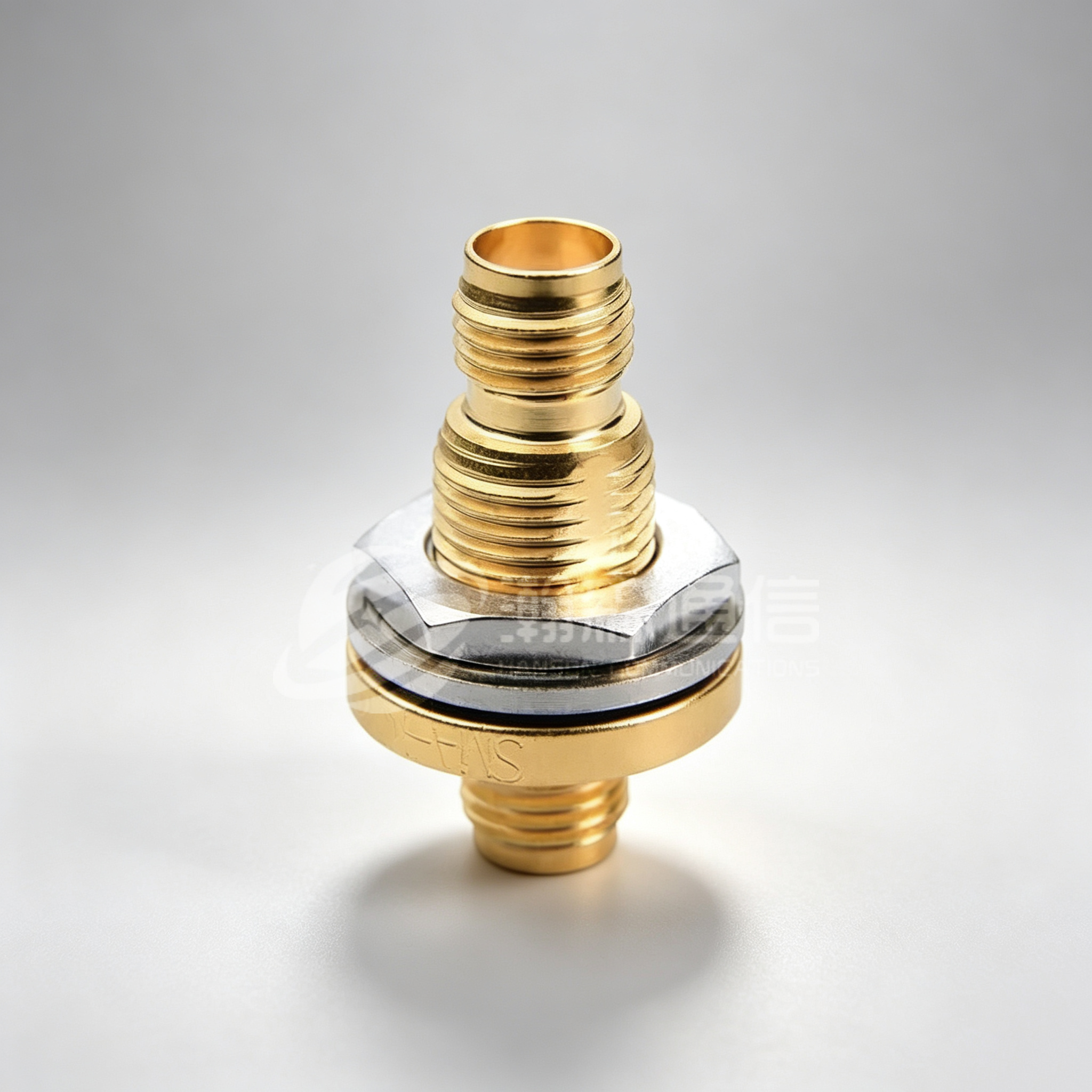
The SMA connector is probably the most widely used threaded RF interface. It is small, reaches 18 GHz in standard quality, and appears on countless modules, antennas, and instruments. For a dependable SMA with consistent plating, look at our SMA connector series for test and communication equipment.
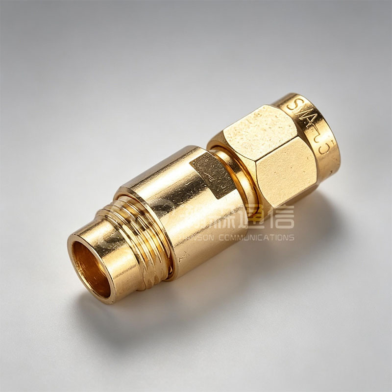 Custom SMA RF Coaxial Connector Supplier, CompanyNingbo Hanson Communication Technology Co., Ltd. is a professional China SMA RF coaxial connectors supplier and SMA connector company, we...View Product →
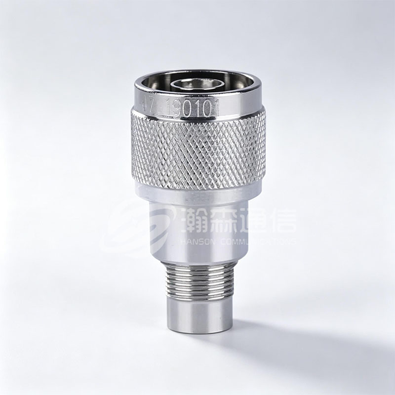
The N-type connector is larger, weather-resistant, and carries power well. Its 18 GHz limit covers most cellular and broadcast bands, making it a staple in outdoor base stations. Our N-type RF coaxial connector is built for repeated mating cycles and low reflection.
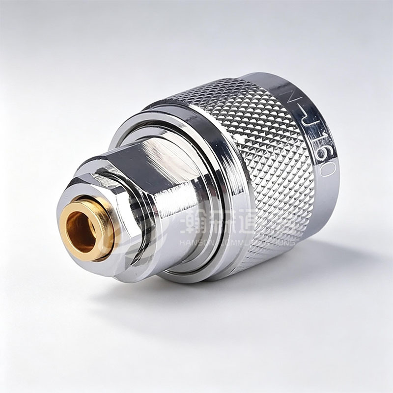 Custom N type RF Coaxial Connector Supplier, CompanyNingbo Hanson Communication Technology Co., Ltd. is a professional China custom N type RF coaxial connector supplier and company, we offe...View Product →
The BNC connector offers fast bayonet coupling and low cost, but its operating range stops around 4 GHz. For laboratory use at lower frequencies, a robust BNC connector for instrumentation and video equipment remains an efficient option.
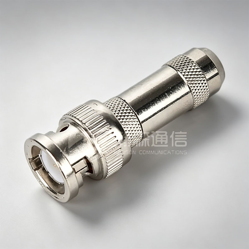 Custom BNC Connector Supplier, CompanyNingbo Hanson Communication Technology Co., Ltd is China BNC Connector supplier and company, offer custom solutions for BNC Connector,The...View Product →
Typical maximum frequency of common RF connectors (GHz)
Based on typical maximum frequency ratings from common RF connector datasheets.
How to Choose the Right RF Connector
The selection process is simpler when you start with the weakest link in your signal chain. Here are the two main groups of criteria to evaluate.
Core selection factors
- Impedance: Always match the system impedance — 50 Ω for general RF, 75 Ω for video and some broadcast.
- Frequency range: Ensure the connector's maximum frequency is at least 10% above your highest signal frequency for a safety margin.
- Power handling: Higher instantaneous power requires larger bodies or better dielectric materials to avoid overheating.
- Mechanical style: Threaded (SMA, N) for vibration; bayonet (BNC) for quick change; push-pull for blind-mate panel connections.
- Mating cycles: For frequent connect/disconnect, choose gold-plated contacts and durable shells.
- Environment: Check temperature, humidity, salt spray, and sealing requirements.
Application-specific considerations
- For outdoor base stations, use N-type connectors because of their weather resistance and lower intermodulation signature.
- For test and measurement, select precision connectors such as 3.5 mm or 2.92 mm with air dielectric; these avoid the dielectric wear found in PTFE-based SMA types.
- For military or aerospace systems, specify plated finishes that meet MIL-STD or space-grade requirements.
- For vacuum or pressure-vessel feedthroughs, use hermetically sealed connectors with glass-to-metal seals to maintain the barrier.
These criteria are not independent – a connector that meets frequency but not environmental requirements will still become the failure point.
Installation and Maintenance Best Practices
Most RF connector failures are caused by mechanical damage or contamination, not by electrical stress. A few disciplined habits will extend the life of both the connector and the connected equipment.
- Clean each mating surface before connecting. Use isopropyl alcohol and lint-free swabs or paper swabs designed for RF connectors.
- Align the connector carefully and push straight in before tightening. Do not rotate the connector body under axial force.
- Tighten to the specified torque. For an SMA connector, this is typically 8 in-lb (0.9 N·m). Always use a torque wrench when available.
- Inspect center pins and threads with a magnifier before each critical mating.
- Cap unused ports with dust caps to prevent debris and bending of the center pin.
For more details on keeping your interconnects clean, see our RF connector cleaning guidelines. If you are working through a new installation, the step-by-step proper installation guide covers the exact sequence.
RF Connector FAQ
What is VSWR and why does it matter?
VSWR (Voltage Standing Wave Ratio) indicates impedance mismatch. A lower value (e.g., 1.1:1) means less signal is reflected and more power is delivered.
What is the difference between SMA and RP-SMA?
RP-SMA has reversed center-conductor polarity. It is commonly used in Wi-Fi equipment to prevent accidental connection with standard SMA antennas.
Do RF connectors need cleaning?
Yes. Dust, oils, and oxidation increase contact resistance and reflection. Clean with IPA and lint-free swabs before critical use.
What are hermetically sealed connectors used for?
They seal a bulkhead or housing against moisture, pressure changes, or gas leakage. Glass-to-metal seals are typical for high-reliability applications.
What does an IP rating mean for RF connectors?
Ingress Protection (IP) rating defines resistance to dust and water. For outdoor RF installations, IP67 or higher is recommended.
How do I know if a connector is 50 Ω or 75 Ω?
Check the color or label. 75 Ω connectors usually have a smaller center pin and a lighter body; measure with a gauge if you are unsure.

Looking For Business Opportunity?
Request for a call today
-

+86-15715730755
-

-

No. 1, Longcao Road, Dongqian Lake Tourism Resort Industrial Zone, Yinzhou District, Ningbo City, Zhejiang, China.
Message
Copyright © Ningbo Hanson Communication Technology Co., Ltd.
