 English
 русский
Industry News

How to Properly Install RF Coaxial Connectors: Steps and Techniques
 2026.01.01
 Industry News
RF coaxial connectors are indispensable components in communication systems, widely used in broadcasting, television, wireless communication, radar, satellite communication, and other fields. These connectors are used to connect coaxial cables to equipment, ensuring the quality and stability of signal transmission. Proper installation of RF coaxial connectors can not only improve the overall performance of the system but also extend the service life of the equipment.
1. Basic Structure of RF Coaxial Connectors
RF coaxial connectors typically consist of the following main parts:
Center conductor: The core part that transmits the signal, usually made of copper or other conductive materials.
Insulating layer: Isolates the center conductor from the outer conductor, usually made of polyethylene or other materials with a high dielectric constant.
Outer conductor: Usually braided copper wire or aluminum foil, acting as a ground wire to transmit current and shield against external electromagnetic interference.
Connector and housing: Provides physical connection and protection, usually made of metal materials (such as brass, stainless steel).
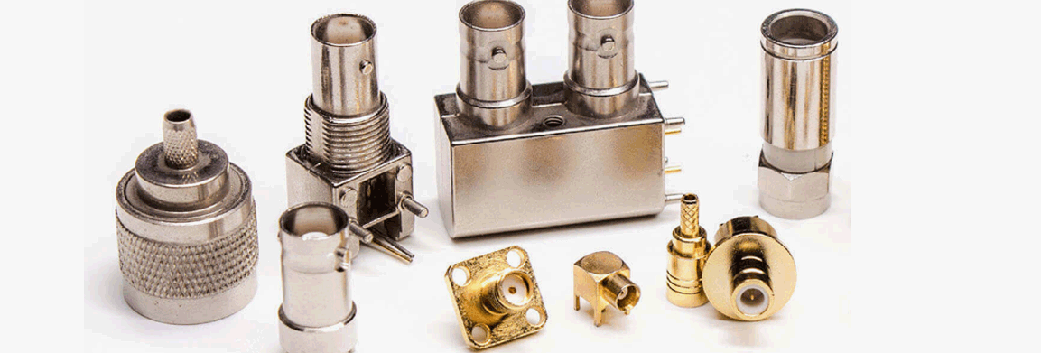
Different types of RF coaxial connectors, such as BNC, SMA, TNC, N-type, etc., have slightly different structures, but the basic installation principles and steps are similar.
2. Steps for Installing RF Coaxial Connectors
(1) Prepare Tools and Materials
Before installation, ensure you have the following tools and materials:
RF coaxial cable (select the appropriate model and length)
RF connector (select the matching connector type, such as BNC, SMA, etc.)
Cable stripping tool: Used to remove the outer insulation layer of the cable, exposing the inner conductor.
Crimping tool: Used to securely connect the connector to the cable.
Electrician's knife, wire stripper: Used to precisely strip the outer insulation of the cable, exposing the inner conductor.
(2) Strip the Outer Insulation of the Cable
Use a cable stripping tool to strip the outer insulation layer of the cable, exposing the inner braided conductor and insulating material. Pay attention to the precision during stripping to avoid damaging the inner conductor or insulation layer. Typically, the stripped length is the installation length of the connector; please refer to the requirements of the specific connector being used for the exact length. Removing the outer braided layer: Gently peel off the outer braided layer of the cable using a tool and fold it outwards. This ensures a good ground connection.
Exposing the center conductor: Carefully remove the inner insulation with a knife to expose the center conductor. The length of the stripped section generally depends on the connector's design requirements.
(3) Inserting the cable into the connector
Insert the prepared cable into the connector's terminal. Ensure the center conductor is accurately aligned and fully inserted into the connector's inner hole, and that the braided layer and outer conductor are in firm contact with the connector's outer casing.
Check alignment during insertion: The center conductor must fully enter the connector's center conductor hole, ensuring no misalignment. The outer braided conductor should be firmly in contact with the connector's casing to ensure a proper ground connection for the signal.
(4) Crimping the connector
Use a crimping tool to crimp the connector. This step is crucial for ensuring a secure connection between the connector and the cable. During crimping, ensure that the crimping tool applies pressure evenly, securely fixing the connector to the cable while avoiding damage to the cable or connector.
Crimping force: The crimping force should be moderate, ensuring a secure connection without excessively compressing the cable or center conductor.
Checking crimping quality: After crimping, check that the connector is secure and not loose.
(5) Checking the overall connection of the connector
After crimping, check the quality of the connection between the connector and the cable. Confirm that the center conductor is tightly connected to the connector's inner core, the outer conductor is in full contact with the connector's casing, and there is no signal leakage.
Checking electrical connection: Use a multimeter to measure the electrical connection of the cable to ensure there are no open circuits or short circuits.
Testing signal transmission: If conditions permit, a signal generator and oscilloscope can be used to test the signal transmission quality and check for signal loss or interference.
(6) Completing the connection and providing protection
After completing the connection, if necessary, use heat shrink tubing, tape, or other materials to protect the cable connection to prevent water or dust from affecting the connection quality.
Using heat shrink tubing: If waterproofing is required, use heat shrink tubing to seal the connector, ensuring that the connection is not affected by moisture or external contamination.
3. Tips for Installing RF Coaxial Connectors
(1) Choose the Right Connector and Cable
Ensure that the connector specifications match the cable being used. Different types of connectors (such as SMA, BNC, N-type, etc.) are suitable for different frequency ranges and application scenarios. Choosing the wrong connector can lead to signal loss or instability.
(2) Pay Attention to Precision When Stripping the Cable
When stripping the outer layer of the cable, ensure that the stripped length is just right, avoiding excessive stripping that exposes too much of the center conductor or damages the insulation layer. Using professional stripping tools can reduce damage to the cable and ensure stable signal transmission.
(3) Avoid Over-Crimping
Over-crimping can damage the center conductor or cause poor contact. Therefore, control the crimping force to ensure that the connector is secure but not over-tightened.
(4) Keep the Cable Clean
During installation, try to avoid contamination of the cable and connector with dust, oil, or other pollutants. These impurities can affect the quality of signal transmission and even cause signal loss.
4. Common Problems and Solutions
(1) Loose Connector
If the connector becomes loose after installation, recheck the crimping to ensure even crimping, or readjust the cable stripping length.
(2) Signal Attenuation
Signal attenuation may be caused by mismatched connectors, incorrect installation, or cable damage. Recheck the compatibility of the cable and connector and ensure installation accuracy.
(3) Poor Electrical Connection
Poor electrical connection may be due to insufficient crimping, the conductor not being fully inserted into the connector, etc. Ensure that the center conductor and outer conductor are tightly connected to the connector.
Installing RF coaxial connectors is a technical task that requires careful operation. Correct installation steps and techniques directly affect the quality of signal transmission and system stability. Through precise stripping, insertion, and crimping operations, ensuring a secure connector connection can effectively improve system performance and reduce signal interference.


Looking For Business Opportunity?
Request for a call today
-

+86-15715730755
-

-

No. 1, Longcao Road, Dongqian Lake Tourism Resort Industrial Zone, Yinzhou District, Ningbo City, Zhejiang, China.
Message
Copyright © Ningbo Hanson Communication Technology Co., Ltd.
