 English
 русский
OEM BNC Connector Supplier

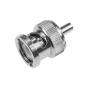
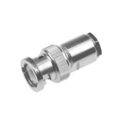
BNC Connector
Description:
The BNC series RF coaxial connector is a bayonet-type RF coaxial connector developed in accordance with the US military standard MIL-C-39012. It has the characteristics of rapid connection and reliable contact, and is one of the most widely used and used connectors in the world. The characteristic impedance of the BNC series RF coaxial connector is divided into 50Ω and 75Ω, and the sizes of the two different impedance connectors are matched.
Parameter:
Main Technical Specifications:
◆ Characteristic Impedance: 50Ω/75Ω
◆ Frequency Range: DC-4GHz(50Ω)/DC-1GHz(75Ω)
◆ Insulation Resistance: ≥5000MΩ
◆ Dielectric Withstand Voltage: 1500V(rms)
◆ Voltage Standing Wave Ratio (VSWR): ≤1.25
◆ Mating Cycles: 500 times


| Dim Ltr |
Millimeters (Inches) | |
| Minimum | Maximum | |
| A | .432 (10.97) | .436 (11.07) |
| B | .378 (9.60) | .382 (9.70) |
| C | .327 (8.31) | .333 (8.46) |
| D | .319 (8.10) | .321 (8.15) |
| F | .204 (5.18) | .208 (5.28) |
| G | .327(8.31) | .335 (8.51) |
| H | .075 (1.91) | 081(2.06) |
| 」 | .186(4.72) | .206 (5.23) |
| K | ------- | .006(0.15) |
| L | .195 (4.95) | ------- |
| M | .081 (2.06) | 087 (2.21) |
| N | .346(8.79) | .356 (9.04) |
| P | ------- | .256 (6.50) |
| R | .015 (0.38) | .030 (0.76) |
| S | .414 (10.52) | ------- |
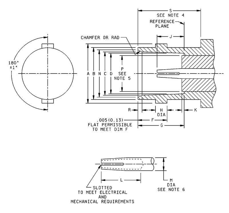
Notes:
1. Dimensions are in inches. Metric equivalents are in parentheses.
2. Metric equivalents are given for general information only.
3. This interface shall meet the gauge requirements as specified in DSCC drawing or specification.
4. Clearance for mating connector coupling nut.
5. "P" dimension applies to that portion (if applicable) of dielectric which extends beyond references planes by dimension K.
6. "M" applies only over length "L".
| Dim Ltr |
Millimeters (Inches) | |
| Minimum | Maximum | |
| A | 385 (9.78) | .390 (9.91) |
| B | Gauge test | |
| D | .052 (1.32) | .054 (1.37) |
| E | .210 (5.33) | .230 (5.84) |
| G | .091(2.31) | .097 (2.46) |
| H | .463 (11.76) | .473 (12.01) |
| H alternate | .394 (10.01) | .400 (10.16) |
| J | .124(3.15) | ------- |
| K | .091(2.31) | .097 (2.46) |
| L | .003 (0.08) | ------- |
| M | .018 (0.46) | .022 (0.56) |
| N | ------- | .025 (0.64) |
| P | .208 (5.28) | ------- |
| Q | .078 (1.98) | ------- |
| T | .045 (1.14) | .049 (1.24) |
| U | .180(4.57) | .184 (4.67) |
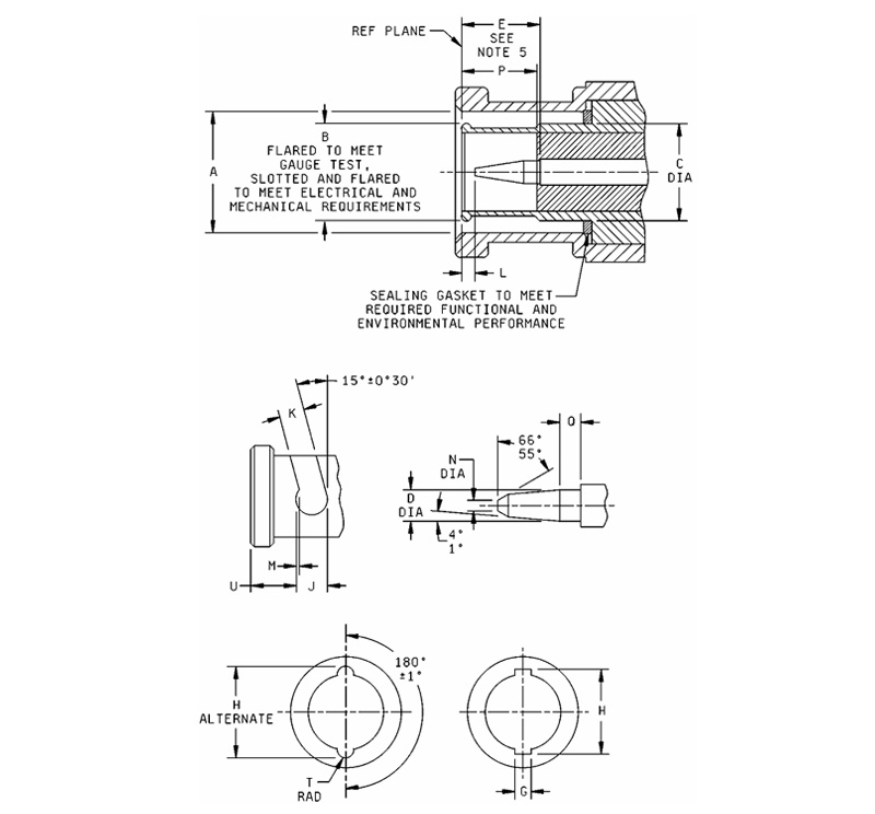
Notes:
1. Dimensions are in inches. Metric equivalents are in parentheses.
2. Metric equivalents are given for general information only.
3. In the mated condition, the longitudinal force of the spring of the coupling mechanism shall exceed the pressure exerted by the sealing gasket by an amount necessary to linsure butting of the outer contacts at the reference plane.
4. This interface shall meet the gauge requirements as specified.
BNC SERIES
-
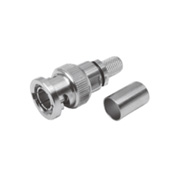
 BNC-JB3
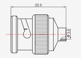
Model Cable type BNC-JB3 SFT-50-3、670-141 -
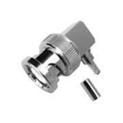
 BNC-KB3
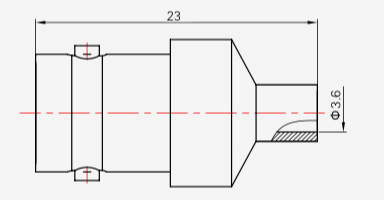
Model Cable type BNC-KB3 SFT-50-3,670-141 -
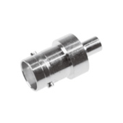
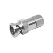
 BNC-KYB2
Model Cable type d BNC-KYB2 SFT-50-2,670-086 Φ2.2 BNC-KYB3 SFT-50-2,670-141 Φ3.6 -
 BNC-J3
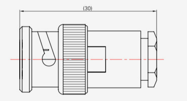
Model Cable type BNC-J3 SYV-50-2-1,RG316 BNC-J4 SYV-50-2-2 BNC-J5,(K)5 SYV-50-3,SFCJ-50-3-51,RG142 BNC-J7 SYV-50-5-1,SFCJ-50-5-51 BNC-J10 SYV-50-7-1,SYV-50-7-2,SFCJ-50-7-51 -
 BNC-J3Y
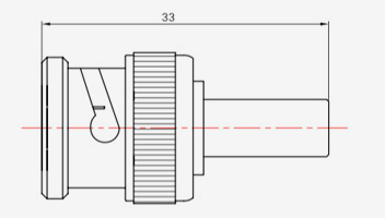
Model Cable type BNC-J3Y SYV-50-2-1 BNC-J5Y SYV-50-3 -
 BNC-J12
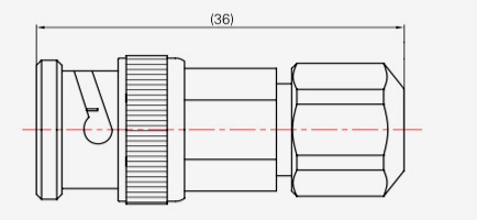
Model Cable type BNC-J12 SYV-75-3 -
 BNC-75J13Y
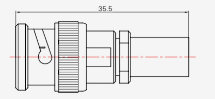
Model Cable type BNC-75J13Y SYV-75-5 -
 BNC-JW3Y
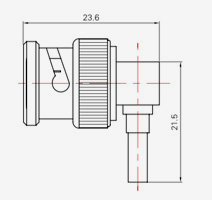
Model Cable type BNC-JW3Y SYV-50-2-1,RG316 -
 BNC-KF3
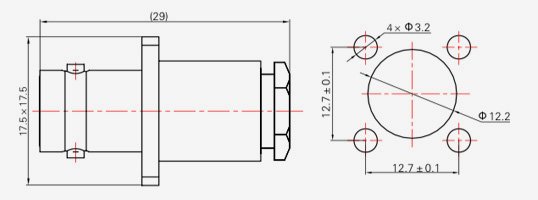
Model Cable type BNC-KF3 SYV-50-2-1,RG316 BNC-KF4 SYV-50-2-2 BNC-KF5 SYV-50-3,SFCJ-50-3-51,RG142 -
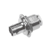 BNC-KY3
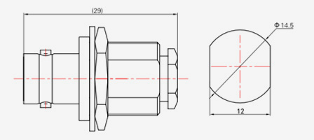
Model Cable type BNC-KY3 SYV-50-2-1,RG316 BNC-KY4 SYV-50-2-2 BNC-KY5 SYV-50-3,SFCJ-50-3-51,RG142 -
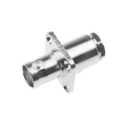
 BNC-KF
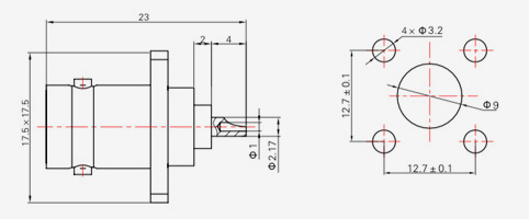
-
 BNC-KY
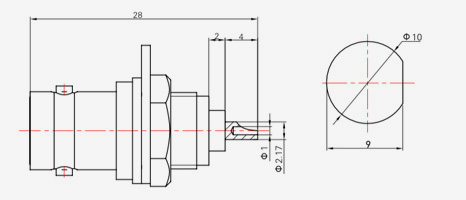
KEEP IN TOUCH


About Us
Ningbo Hanson Communication Technology Co., Ltd.
Ningbo Hanson Communication Technology Co., Ltd. is China BNC Connector Supplier and Custom BNC Connector Company. We are a manufacturer specializing in the production, processing, and trade of communication components, with more than 30 years of experience in RF coaxial connectors, adapters, and cable assemblies.
The company has now developed its own machining workshop, electroplating workshop, assembly workshop, and a group of stable and reliable suppliers. The company's purpose is to provide customers with high-quality products. The main products
are RF coaxial connectors, adapters, high-frequency cable assemblies, and low intermodulation cable assemblies. In addition, the company can also provide services for customers with customized needs to meet customers' special requirements for products.
The company's products are widely used in aerospace, communication base stations, medical equipment, and other high-tech fields. At the time of enterprise reform, innovation, development, and growth, the company took the initiative to join the ISO9001 international quality management system and continuously improved the management level so as to provide more satisfactory products and services to new and old customers.
Latest News
-
* { margin: 0; padding: 0; box-sizing: border-box; } body { background: #f5faff; font-family: '...
READ MORE -
Quick Answer: What to Look for in a Hermetic Connector Manufacturer Choosing the right Hermetically Sealed Connector partner generally comes down to five practical checkpoints: gl...
READ MORE -
The Direct Answer: What Engineers Should Verify Before Buying an RF Adapter Before selecting any RF Coaxial Adapter, engineers should confirm four values first: impedance match (t...
READ MORE -
Before purchasing RF coaxial adapters, buyers must understand three non-negotiable fundamentals: connector type compatibility, impedance matching, and frequency range adequacy. Se...
READ MORE
Looking For Business Opportunity?
Request for a call today
-

+86-15715730755
-

-

No. 1, Longcao Road, Dongqian Lake Tourism Resort Industrial Zone, Yinzhou District, Ningbo City, Zhejiang, China.
Message
Copyright © Ningbo Hanson Communication Technology Co., Ltd.
