 English
 русский
Industry News

What is an RF coaxial connector?
 2025.09.10
 Industry News
1. The Function of an RF Coaxial Connector
RF coaxial connectors are key electronic components used to transmit high-frequency signals. They are primarily used to reliably connect coaxial cables to devices, ensuring efficient and stable transmission of RF signals, thereby ensuring stable and reliable signal transmission. RF coaxial connectors are commonly used in communications equipment, television, broadcasting, wireless networks, and other fields. Their core function is to maintain signal integrity, reduce transmission loss and interference, and provide good impedance matching, enabling smooth transmission of high-frequency signals in applications such as communications systems, test equipment, radar, and antennas.
RF coaxial connectors play a vital role in wireless communications, aerospace, military electronics, and medical equipment. For example, in 5G base stations, they connect antennas and RF modules, ensuring high-quality signal transmission and reception. In test and measurement equipment, they connect to spectrum analyzers or network analyzers, ensuring accurate test data. In satellite communications and radar systems, they must withstand harsh environmental conditions while maintaining stable signal transmission.
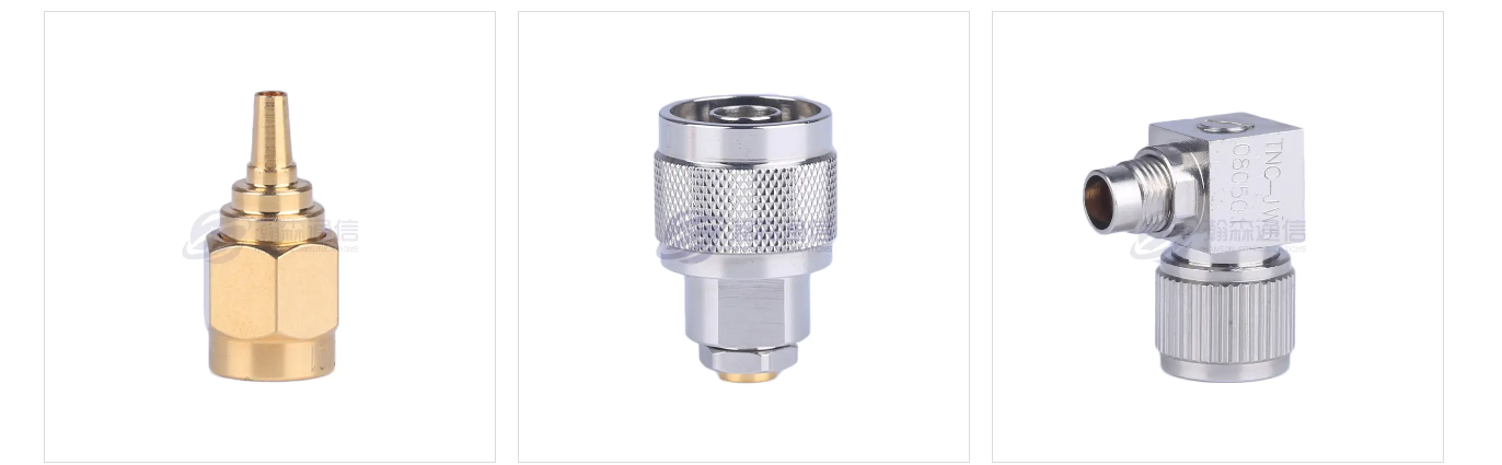
RF coaxial connectors typically utilize a metal shielded structure, with the inner conductor transmitting the signal and the outer conductor providing electromagnetic shielding to prevent external interference and signal leakage. High-quality connectors feature low insertion loss, high shielding effectiveness, corrosion resistance, and vibration resistance, and can accommodate diverse frequency ranges (from low frequencies to millimeter waves). Furthermore, depending on application requirements, connectors can adopt various interface styles, such as threaded (SMA), snap-on (BNC), or push-pull (MCX), to meet the mechanical strength and convenience requirements of different scenarios. RF coaxial connectors are essential components in high-frequency electronic systems. Their performance directly impacts the stability and efficiency of the entire communication link, making them a critical component for the proper operation of modern wireless technologies, defense equipment, and industrial automation.
The operating principle of RF coaxial connectors is based on the propagation characteristics of electromagnetic waves in concentric conductor structures. Through a precisely designed coaxial structure, they achieve low-loss, high-fidelity transmission of high-frequency signals. Their core principle is to create a closed electromagnetic field transmission channel: the center conductor carries the signal current, while the outer conductor acts as an electromagnetic shield, separated by an insulating dielectric that maintains a constant impedance. When a high-frequency electrical signal is injected into the inner conductor, it excites transverse electromagnetic waves (TEM waves) in the insulating medium between the inner and outer conductors. This electromagnetic energy is strictly confined to the coaxial space, effectively suppressing signal radiation loss and external interference. The connector's mechanical interface ensures conductor continuity and impedance matching through precise contact, preventing signal reflections at the connection point due to impedance changes, ultimately ensuring stable transmission of high-frequency signals between devices. This structural design enables RF coaxial connectors to maintain excellent signal integrity even in gigahertz-level high-frequency environments.
The core design of RF coaxial connectors is based on coaxial transmission line theory, which utilizes the electromagnetic field distribution between the inner and outer conductors to achieve signal transmission:
Center conductor (inner conductor): Transmits high-frequency signals and is typically made of copper or gold-plated material to reduce resistive losses.
Outer conductor (shield): Encloses the inner conductor, providing electromagnetic shielding to prevent signal interference and radiation leakage.
Insulation medium (dielectric layer): Separates the inner and outer conductors, maintaining a stable impedance (typically 50Ω or 75Ω), and reducing signal reflections.
Connection mechanism: Use threaded (e.g., SMA), snap-on (e.g., BNC), or push-pull (e.g., MCX) connectors to ensure mechanical stability and good electrical contact.
When the connectors are properly mated, the signal is transmitted through the inner conductor, and the outer conductor forms a closed loop, ensuring impedance continuity during signal transmission and reducing standing wave ratio (VSWR) and insertion loss.
2.Features and Advantages of RF Coaxial Connectors
RF coaxial connector, as the core component of high-frequency signal transmission, has shown significant advantages in performance, reliability and adaptability due to its unique structure and material design. Its advantages are mainly reflected in the following aspects:
(1). High-frequency transmission performance
Wideband coverage: supports an extremely wide frequency range from DC to millimeter wave (above 40GHz), meeting the needs of high-frequency applications such as 5G and satellite communications.
Low insertion loss: uses highly conductive materials (such as gold-plated inner conductors) and low dielectric loss insulation media to significantly reduce signal attenuation.
Excellent impedance matching: strictly controlled 50Ω or 75Ω characteristic impedance minimizes signal reflection.
(2). Reliability and stability
Strong electromagnetic shielding: multi-layer metal shielding structure (such as threaded locking, metal shell) effectively suppresses electromagnetic interference (EMI) and RF leakage.
High mechanical durability: precision-machined contact interface (such as elastic pin design) ensures stable contact after thousands of plugging and unplugging. Wide environmental adaptability: Optional special treatments such as waterproof (IP67), high temperature resistance (-65℃~+165℃), and salt spray resistance are available, making it suitable for harsh environments such as military and aerospace.
(3). Diverse designs adapt to multiple scenarios
Rich interface types: including threaded (SMA, N-type), snap-on (BNC), push-pull (MCX/MMCX), etc., to meet different installation requirements.
Flexible power capacity: Customizable from low power to kilowatt-level high power, adaptable to different load scenarios such as communication base stations and radars.
Miniaturization trend: With the development of 5G and the Internet of Things, micro connectors achieve high-performance transmission in limited spaces.
(4). Convenience and standardization
Quick connection design: For example, the one-handed snap-on operation of some products can greatly improve installation efficiency.
International standard compatibility: Complies with international standards such as MIL-STD and IEC to ensure universal interchangeability with mainstream equipment interfaces.
(5) Wide range of applications
From consumer electronics (mobile phone antennas) to industrial applications (base station RF modules) to high-tech fields (phased array radars, satellite payloads), RF coaxial connectors have become basic components in industries such as wireless communications, test and measurement, and national defense science and technology due to their signal fidelity and environmental robustness.
RF coaxial connectors, through the deep integration of materials science, precision mechanics, and electromagnetic design, achieve the core requirements of "low loss, high shielding, and long life" in high-frequency signal transmission, and are the key guarantee for the efficient and reliable operation of modern electronic systems.
RF coaxial connectors are widely used in industries requiring high-frequency signal transmission:
Communications: Antenna feeder connections for 5G base stations, fiber-optic communications, and satellite communications.
Aerospace & Defense: High-reliability connections for radar systems, missile guidance, and airborne communications equipment.
Test & Measurement: Calibration and signal testing for instruments such as vector network analyzers (VNAs) and spectrum analyzers.
Consumer Electronics: RF modules for Wi-Fi routers, smartphones (such as antenna interfaces), and Internet of Things (IoT) devices.
Medical Equipment: Signal transmission for MRI radio frequency coils and microwave therapy devices.
Automotive: Signal connections for in-vehicle radar (such as millimeter-wave radar) and GPS navigation systems.
3.How to Choose the Right RF Coaxial Connector
Choosing the right RF coaxial connector requires considering multiple factors, including electrical performance, mechanical characteristics, environmental compatibility, and the application scenario.
(1). Clarify electrical performance requirements
Operating frequency range: The upper frequency limits supported by different connectors vary significantly (e.g., BNC ≤ 4 GHz, SMA ≤ 18 GHz, and 2.92 mm connectors up to 40 GHz). Matching the system's signal frequency band is essential.
Impedance matching: Communication systems often use 50 Ω (e.g., base stations and radar), while video transmission systems often use 75 Ω (e.g., broadcast equipment). Choosing the wrong impedance can lead to signal reflections.
Insertion loss and VSWR: For high-frequency applications (e.g., millimeter-wave), low-loss designs (e.g., air-dielectric connectors) are preferred, and the VSWR should be as close to 1:1 as possible.
Power handling: For high-power applications (e.g., radar transmitters), select 7/16 or N-type connectors to avoid failure due to overheating.
(2). Evaluate mechanical and interface characteristics
Connector type:
Threaded connectors (SMA, N-type): Preferred for high-vibration environments (e.g., in-vehicle and airborne equipment) due to their high resistance to loosening. Snap-on connectors (BNC): Suitable for testing scenarios requiring frequent plugging and unplugging (e.g., laboratory oscilloscopes). They are convenient to use but prone to falling off.
Microminiature connectors (MMCX, MCX): Compact solutions for space-constrained devices (e.g., smartphone modules).
Plug-in life: Industrial-grade connectors typically last over a thousand plug-in and plug-out cycles, while consumer-grade connectors may only last a few hundred.
Cable compatibility: Confirm that the connector interface matches the coaxial cable type and wire diameter.
(3). Consider environmental adaptability
Protection rating: Outdoor or humid environments require IP67 or higher waterproof rating (e.g., 5G base station antenna interfaces).
Temperature and corrosion resistance: Aerospace or military applications require high-temperature resistance (-65°C to +200°C) and salt spray resistance (e.g., gold-plated stainless steel).
Vibration/shock resistance: Mobile platforms such as vehicles and aircraft require connectors with locking mechanisms (e.g., three-screw SMA) or spring-loaded contact designs.
(4). Matching the Application Scenario
Communications Equipment: 5G base stations prefer N-type (high power) and SMA (miniaturized) connectors. Millimeter-wave bands require 2.92mm or K-type connectors.
Test and Measurement: Use precision connectors (such as 3.5mm) for high-frequency testing to avoid errors introduced by low-precision connectors like BNCs.
Consumer Electronics: Wi-Fi modules often use U.FL (ultra-miniature) connectors, but a trade-off between cost and signal loss is required.
Military/Aerospace: Choose high-reliability models with full metal housings and gold-plated contacts that meet MIL-STD-348 standards.
(5). Other Key Factors
Cost and Lead Time: High-end connectors (such as millimeter-wave connectors) are expensive, so consider your budget and supply chain stability.
Degree of Standardization: Prefer universal connectors (such as SMA) to avoid niche models that may cause maintenance difficulties.
Mounting Method: PCB mounting, panel mounting, or direct cable connection require different configurations (such as right-angle or straight connectors).
Selection Process Example
Determine requirements: For example: 5G small base station radio unit, 3.5 GHz frequency, outdoor installation, waterproof.
Screening parameters:
Frequency: 3.5 GHz → Either SMA or N-type are acceptable.
Environment: IP67 waterproof → Select N-type (more reliable thread seal).
Power: Medium → N-type offers ample power margin.
Verify compatibility: Confirm that the N-type connector matches existing cables (such as LMR-400) and device ports.
4.Common problems of RF coaxial connectors
Over long-term use, RF coaxial connectors may develop various problems due to factors such as design, installation, and environmental factors, impacting signal transmission quality. Common problems with RF coaxial connectors are often related to impedance matching, mechanical strength, shielding effectiveness, and environmental adaptability. Product failure rates can be reduced through appropriate selection (e.g., matching frequency and power), standardized installation (e.g., torque control), and regular maintenance (e.g., cleaning contact surfaces).
(1). High signal loss or low transmission efficiency
Possible causes:
Connector impedance mismatch (e.g., mixing 50Ω and 75Ω devices).
Aging connectors or cables, oxidized conductors, and poor contact.
Loose or partially tightened connections, causing signal reflections.
Using low-quality connectors or cables, resulting in excessive insertion loss.
Solution:
Ensure that all connectors and cables in the system have consistent impedance (typically 50Ω or 75Ω).
Inspect connector contact surfaces for oxidation or contamination, and clean or replace if necessary.
Use a torque wrench to tighten threaded connectors (e.g., SMA, N-type) to the standard torque. Choose low-loss cables and high-performance connectors (such as gold-plated contacts).
(2). Signal Interference or Loud Noise
Possible Causes:
Poor connector shielding, allowing electromagnetic interference (EMI) to penetrate.
Poor grounding of the connector housing, causing common-mode interference.
Nearby sources of strong electromagnetic radiation (such as motors and inverters).
Damaged cables or connectors, with broken shielding.
Solution:
Select connectors with full metal housings and high shielding effectiveness.
Ensure that the connector housing is properly grounded to the device chassis.
Use double-shielded or triple-shielded coaxial cables to enhance interference immunity.
Inspect the cable for damage and replace if necessary.
(3). Loose Connectors or Poor Contact
Possible Causes:
Mechanical wear from excessive plugging and unplugging (such as a failed BNC spring).
Threads not tightening properly in vibration or shock environments (such as in vehicles or aircraft).
The connector male and female connectors are mismatched or have excessive tolerances.
Solution:
For frequent plugging and unplugging scenarios, choose connectors with a long lifespan (such as an SMA connector with a 5000-cycle plug-in rating). Use connectors with locking mechanisms (such as triple-screw SMAs) in vibrating environments.
Ensure that connector models match; avoid mixing different brands or specifications.
(4). Connector damage (e.g., breakage, deformation)
Possible causes:
Excessive mechanical stress (e.g., excessive bending of the cable, resulting in broken connector solder joints).
Using improper installation tools, resulting in loosening of the housing threads.
Material aging or environmental corrosion (e.g., salt spray, high temperatures).
Solution:
Avoid applying lateral force to the connector during installation and use right-angle connectors to minimize bending.
Use specialized tools (e.g., torque wrenches) to install threaded connectors.
Select corrosion-resistant materials (e.g., gold-plated stainless steel) for harsh environments.
(5). Impedance discontinuity leading to signal reflections
Possible causes:
Impedance mismatch between the connector and cable (e.g., a 50Ω connector with a 75Ω cable).
Internal structural defects in the connector (e.g., uneven dielectric layer).
Incomplete mating of the connector, resulting in air gaps.
Solution:
Ensure consistent impedance across the entire transmission path (including the connector, cable, and device). Choose connectors with high-precision machining (such as those specified in the military standard MIL-STD-348).
Fully tighten the connector to avoid impedance fluctuations caused by misalignment.
(6). Waterproof performance failure
Possible causes:
Waterproof seals are aged or damaged.
Threads are not tightened or the sealant has expired.
Connector design is not suitable for humid environments.
Solution:
Inspect the seals regularly. For outdoor applications, choose connectors rated IP67 or higher.
Use waterproof tape or silicone to enhance sealing.
Select waterproof models with O-rings (such as N-type waterproof connectors).
(7). Resonance issues in high-frequency applications
Possible causes:
The connector exhibits parasitic resonance at high frequencies (e.g., design flaws).
The connector and PCB layout do not match, generating standing waves.
Solution:
Select a connector that supports higher frequencies (e.g., 2.92mm instead of SMA).
Optimize PCB impedance matching to avoid discontinuities in transmission line lengths.
Summary table of common problems with RF coaxial connectors:
| Symptom | Possible Cause | Solution |
| Large signal loss | Impedance mismatch (e.g., mixing 50Ω/75Ω), contact oxidation, loose plugs, low-quality cables/connectors | Use standardized impedance standards, clean contact surfaces, properly install, and use low-loss materials (e.g., gold-plated conductors) |
| Signal interference/noise | Poor shielding, ineffective grounding, nearby strong electromagnetic sources, or damaged cable shields | Use fully metal shielded connectors, ensure good grounding, keep away from interference sources, and replace damaged cables |
| Loose connectors | Wear from plugging and unplugging (e.g., BNC clip failure), loose threads due to vibration, male and female connector mismatch | Select models with long plug-in life (e.g., SMA). Use thread locks (e.g., triple screws) for vibration environments. Verify interface compatibility |
| Mechanical damage | Excessive cable bending, improper installation tools, material aging/corrosion | Avoid lateral force, use a torque wrench, and choose corrosion-resistant materials (e.g., gold-plated stainless steel) for harsh environments |
| Impedance discontinuity | Impedance mismatch between connector and cable, internal structural defects, incomplete mating | Ensure consistent impedance across the entire link. Use high-precision connectors (MIL-STD) to ensure a secure mating connection |
| Waterproofing failure | Aging seals, loose threads, non-waterproof design | Replace seals regularly. For outdoor use, choose IP67 or higher rating. Strengthen sealing (e.g., waterproof adhesive) |
| High-frequency resonance | Parasitic resonance in connectors, PCB layout mismatch | Upgrade to a high-frequency model (e.g., 2.92mm) and optimize PCB impedance continuity |
| Abnormal temperature performance | High temperatures can cause dielectric deformation and low-temperature material cracking | Use wide-temperature materials (e.g., PTFE dielectric) and avoid exceeding specifications |
| RF leakage | Poor housing seals and incomplete connector shielding | Check housing integrity and choose a fully enclosed design (e.g., threaded lock + metal housing) |
| Increased contact resistance | Contact oxidation, plating wear, insufficient insertion and removal force | Clean or replace connectors. Choose gold/silver-plated contacts to ensure insertion and removal force meets standards |
5.Maintenance standards for RF coaxial connectors
The performance of RF coaxial connectors directly affects the quality of signal transmission, so regular maintenance is required to ensure long-term stable operation. The following are key maintenance standards and operating specifications:
(1). Regular inspection and cleaning
Appearance inspection: Check whether the connector shell is deformed, cracked or corroded (such as rust, oxidation), especially the metal parts and sealing rings.
Contact surface cleaning: Use anhydrous alcohol and non-woven cloth to clean the inner conductor and pins to remove the oxide layer, dust or oil. Avoid using abrasive materials (such as sandpaper) to prevent damage to the plating.
Interface status confirmation: Ensure that the male and female connectors are plugged in smoothly without looseness or misalignment. Threaded connectors (such as SMA, N type) should check whether the threads are intact to avoid slipping.
| Inspection Items | Standard Requirements |
| Casing Integrity | No cracks, deformation, or rust (especially in outdoor or highly corrosive environments) |
| Connector Cleanliness | Inner/outer conductors free of oxidation, dirt, grease, or foreign matter (such as dust or welding slag) |
| Sealing | Waterproof connector sealing rings (O-rings) free of aging or damage, and threaded connections free of looseness |
| Cable Connection Status | No cracks or looseness at the weld/crimp joints between the cable and connector, and no delamination of the shielding layer |
Cleaning Procedure
Power-off Operation: Ensure the device is powered off to prevent static electricity damage.
Physical Cleaning: Use an air gun to remove large impurities, then gently wipe the contact surfaces with a cotton swab dipped in alcohol.
Oxidation Treatment: If the coating is oxidized (e.g., blackened), lightly polish it with an eraser or a dedicated cleaner.
Drying: Air dry or tumble dry at low temperature (≤60°C) to avoid residual alcohol.
(2). Electrical performance test
Impedance matching verification: Use a network analyzer or TDR (time domain reflectometer) to detect the impedance continuity of the connector and cable to ensure there is no sudden change (VSWR ≤ 1.5 is best). Insertion loss monitoring: High-frequency applications require regular testing of signal loss. If the loss increases abnormally (e.g., exceeding 20% of the nominal value), it is necessary to check for connector or cable aging issues. Shielding effectiveness check: Use an RF leakage tester or near-field probe to test the connector shielding performance to ensure there is no electromagnetic leakage.
(3). Mechanical performance maintenance
Plug-in and pull-out operation specifications: Avoid rough plug-in and pull-out. Snap-on connectors (such as BNC) need to press the clamp before pulling out. Threaded connectors should be tightened with a torque wrench according to the standard torque (such as SMA recommends 0.5~0.8N·m).
Anti-loosening measures: In a vibration environment (such as vehicle-mounted or airborne equipment), threaded connectors need to be equipped with anti-loosening glue or locking washers, and the tightening status should be checked regularly.
Cable protection: Avoid excessive bending of the cable (minimum bending radius ≥ 5 times the cable outer diameter) to prevent the connector solder joints from breaking or the shielding layer from being damaged.
(4). Environmental adaptability maintenance
Waterproof and moisture-proof treatment: Waterproof connectors (IP67 and above) used outdoors or in humid environments need to regularly check the elasticity of the sealing ring and replace it in time after aging; non-waterproof interfaces can be coated with silicone grease to enhance protection.
Corrosion resistance maintenance: In salt spray, acid and alkali environments, use stainless steel or gold-plated shell connectors and wipe the metal surface with rust inhibitor regularly. Temperature adaptability: In high-temperature environments (such as base station radio frequency units), it is necessary to ensure that the connector dielectric material (such as PTFE) does not deform. In low-temperature environments (such as Arctic equipment), it is necessary to avoid brittle cracking of plastic parts.
(5). Life management and replacement cycle
Plug-in life monitoring: Record the number of high-frequency plug-in and pull-out times and replace in advance when the life is approaching.
Replacement of aging parts: When there is poor contact, shielding layer damage or insulation performance degradation, the connector must be replaced and reuse after repair is prohibited.
Spare parts standardization: The same brand and model connectors should be used as much as possible in the same system to avoid compatibility issues caused by mixed use.
RF coaxial connector life management and replacement cycle table:
| Connector Type | Nominal Plug and Unplug Life | Key Life Indicators | Recommended Replacement Cycle | Replacement Trigger | Life Extension Measures |
| SMA Series | 3000-5000 cycles | Thread wear and dielectric layer aging | 5 years (normal use) 3 years (outdoor environment) | 1.Thread stripping 2. VSWR > 1.83. Insertion and extraction torque variation > 30% | 1. Use a torque wrench for proper installation 2. Avoid overtightening |
| N Type | 1000-2000 cycles | Thread seals and housing corrosion | 8 years (fixed installation) 5 years (mobile equipment) | 1. Waterproofing failure 2. Housing rust > 30% 3. Insertion loss increased by 0.5dB | 1. Replace the seal regularly 2. Apply surface anti-rust treatment |
(6). Documentation and records
Maintenance log: Record the date of each inspection, test data (such as VSWR, insertion loss), and replacement part model for easy traceability analysis.
Fault case library: Summarize typical faults (such as high resistance caused by oxidation, looseness caused by vibration) to optimize preventive maintenance strategies.
6.How to extend the service life of RF coaxial connectors
RF coaxial connectors are key components for high-frequency signal transmission, and their lifespan directly affects system stability. Their service life can be extended through reasonable selection, installation, use, and maintenance.
(1). Correct selection and matching
Frequency and power matching: Select connectors that meet the system's operating frequency and power requirements (e.g., N-type is preferred for 5G base stations, and SMA is preferred for high-frequency testing).
Impedance consistency: Ensure that the impedance of connectors, cables, and equipment is consistent (usually 50Ω or 75Ω) to avoid performance degradation caused by signal reflection.
Environmental adaptability: For outdoor or harsh environments (high temperature, salt spray, vibration), waterproof (IP67), corrosion-resistant (gold-plated stainless steel), or reinforced connectors should be selected.
(2). Standard installation of RF coaxial connectors
1) Pre-installation Preparation
Check the compatibility of the connector and cable.
Confirm that the connector model (e.g., SMA, Type N) is compatible with the cable type (e.g., RG-58, LMR-400).
Verify that the impedance (50Ω/75Ω), frequency range, and power handling meet the requirements.
Check component integrity.
Inspect the connector housing, threads, and pins for deformation, cracks, or oxidation.
Ensure that the cable shield is not damaged and that the inner conductor is not bent or broken.
Clean the contact components.
Use anhydrous alcohol and a non-woven cloth to clean the inner conductor and jack to remove oil, dirt, or oxidation.
Do not use sandpaper or hard objects to scratch gold/silver plated contacts.
2) Connector and Cable Assembly Specifications
Cable Stripping and Pretreatment
Use a dedicated stripping tool to strip the cable jacket, shield, and insulation to the length required by the connector.
Ensure the inner conductor is the appropriate length, avoiding excessive length (e.g., bending) or excessive length (e.g., poor contact). Soldering or Crimping Operations
Solder Connectors:
Use a constant-temperature soldering iron (recommended temperature: 300-350°C) and complete the soldering quickly to avoid overheating and damaging the dielectric.
Solder joints should be smooth and burr-free to prevent short circuits or impedance changes.
Crimp Connectors:
Use a matching crimping tool to ensure even crimping pressure and secure contact between the shield and the housing.
Post-Assembly Inspection:
Use a multimeter to check for continuity and confirm there are no short circuits or breaks.
Gently pull on the cable to check the mechanical stability of the connector and cable.
3) Connector Docking and Securing
Alignment and Mating: Ensure the male and female connectors are aligned strictly to avoid bending or damaging the pins due to skewed insertion.
Push-on connectors (such as BNC) should lock with an audible click. Threaded connectors (such as SMA) should be manually tightened before tightening. Tightening Threaded Connectors
Use a torque wrench to tighten to the standard torque (example):
SMA connector: 0.5-0.8 N·m
N-type connector: 1.0-1.5 N·m
Do not overtighten to avoid damaging the threads or deforming the media.
Anti-loosening measures
In vibrating environments (such as those used in vehicles or aircraft), threaded connectors should be equipped with spring washers or anti-loosening adhesive.
Snap-on connectors (such as BNC) can be wrapped with anti-loosening tape to enhance retention.
4) Precautions during Operation
Plug-in and unplugging procedures
Do not plug or unplug while powered on: High-frequency signals may cause arcing and damage the contact surfaces.
When unplugging: For snap-on connectors, press the clamp firmly; for threaded connectors, completely loosen them before disconnecting.
Avoid mechanical stress
When routing cables, allow a bend radius (≥5 times the cable diameter) to prevent stress at the base of the connector.
Use cable ties or clamps to secure the cable to prevent it from dangling. Environmental Adaptability
Humid Environments: After installing waterproof connectors (IP67), check that the sealing ring is securely tightened.
High-Temperature Environments: Avoid prolonged exposure of the connector to excessive temperatures (e.g., PTFE dielectric is limited to 165°C).
5) Post-Installation Verification and Testing
Electrical Performance Testing
Use a network analyzer to measure the standing wave ratio (VSWR); the normal value should be ≤1.5.
Measure insertion loss. If abnormal, check for poor contact or cable damage.
Mechanical Stability Check
Gently shake the connector to confirm there is no looseness or unusual noise.
Perform a vibration test (e.g., a 5-500Hz frequency sweep) in a vibrating environment.
(3). Regular cleaning and maintenance
Contact surface cleaning: Regularly clean the inner conductor and pins with anhydrous alcohol and non-woven cloth to remove the oxide layer or dirt. Avoid using abrasive materials (such as sandpaper) to prevent damage to the gold/silver plating. Check the sealing: Waterproof connectors need to regularly check whether the O-ring or sealant is aging and replace it if necessary. Shielding layer inspection: Ensure that the cable shielding layer is not damaged to prevent electromagnetic interference (EMI) from affecting the signal quality.
| Maintenance Items | Operational Standards | Tools/Materials | Cycle | Precautions |
| Visual Inspection | Inspect the housing, threads, and pins for deformation, oxidation, or corrosion | Magnifying glass, flashlight | Monthly (for harsh environments) | Focus on inspecting the waterproof seals of outdoor equipment. Immediately address any rust |
| Every three months (for normal environments) | ||||
| Contact surface cleaning | Wipe the inner conductor and pins with anhydrous alcohol (99%) and a non-woven cloth to remove any oxide or dirt | Anhydrous alcohol, non-woven cloth, anti-static brush | Every six months (after frequent plugging and unplugging) | Do not use chlorinated solvents or abrasive materials (such as sandpaper) to avoid damaging the gold plating |
| Thread Lubrication | Apply a small amount of silicone grease (such as DC4) to the threaded joint to prevent seizure and oxidation | High-temperature silicone grease, cotton swab | Once per year | Avoid contamination of the inner conductor with grease. Apply only to the threads |
| Shield Inspection | Check the cable shield for damage or peeling, and replace the cable if necessary | Multimeter, visual inspection | Once every six months | Shield breaks can cause signal leakage and require prompt repair |
| Waterproof Seal Testing | Perform a water spray test on connectors rated IP67 or above to confirm no water leakage | Spray bottle (simulates water spray), drying oven | Once every three months (for outdoor equipment) | After testing, thoroughly dry the device to prevent residual moisture from causing a short circuit |
| Electrical Performance Testing | Use a network analyzer to measure VSWR (≤1.5) and insertion loss (≤0.3dB) | Network analyzer, calibration kit | Once annually (quarterly for critical systems) | If any abnormality occurs, troubleshoot the connector or cable, prioritizing the contact surfaces |
(4). Avoid environmental damage
Moisture and corrosion resistance:
Gold-plated or stainless steel shell connectors should be used in humid or salt spray environments, and rust inhibitors should be applied regularly.
Non-waterproof connectors can be temporarily protected with heat shrink tubing or waterproof tape.
Temperature management:
In high-temperature environments (such as base station radio frequency units), ensure that the connector dielectric material (such as PTFE) is not deformed.
In extremely low-temperature environments (such as Arctic equipment), avoid brittle cracking of plastic parts.
(5). Reasonable use and life management
Reducing frequent plugging and unplugging:
For high-frequency plugging and unplugging scenarios (such as test equipment), choose high-life models (such as SMA plugging and unplugging more than 5000 times).
If necessary, use adapters or extension cables to reduce the number of plugging and unplugging of the main connector.
Periodic performance testing:
Use a network analyzer to detect VSWR (standing wave ratio) and insertion loss, and replace them in time if abnormal.
Spare parts replacement strategy:
Replace in advance when approaching the nominal plugging and unplugging life (such as SMA 5000 times) or when poor contact occurs.
(6) Fault Prevention
Avoid mixing different brands:
Try to use the same connector model in the same system to avoid wear caused by tolerance mismatch.
Maintain a maintenance log:
Record each maintenance time, test data, and replacement records to facilitate analysis of life trends.
7.RF Coaxial Connector Frequently Asked Questions (FAQ)
(1). Why does the connector have poor contact?
Possible reasons: Pin oxidation or contamination (clean with alcohol). Thread not tightened (SMA requires 0.5~0.8N·m torque). Mechanical damage (such as bent pins, need to be replaced).
(2). How to avoid excessive signal loss?
Ensure impedance consistency (50Ω/75Ω do not mix). Select low-loss cables (such as LMR-400). Clean the contact surface regularly to avoid oxidation. (3). Can connectors of different brands be mixed? Not recommended! Tolerance differences between different brands may cause: Poor pin contact. Impedance discontinuity (signal reflection). Reduced mechanical strength (such as thread slippage).
(3). How to select connectors for high temperature environments?
Select high-temperature resistant PTFE as the dielectric material (limited to 165℃). Use stainless steel or gold-plated metal shells. Avoid plastic parts (easy to deform).
(4) How to choose an RF coaxial connector?
The following factors need to be considered:
Frequency range: BNC (≤4GHz), SMA (≤18GHz), N-type (≤11GHz), 2.92mm (≤40GHz).
Impedance matching: 50Ω (communication system) or 75Ω (video transmission).
Power capacity: For high power, choose N-type or 7/16-type.
Environmental requirements: Waterproof type for outdoor use (IP67), corrosion-resistant gold-plated type for military use.
(5) How to detect connector failure?
Visual inspection: oxidation, deformation, cracks.
Multimeter test: conductivity and insulation resistance.
Network analyzer: measure VSWR and insertion loss.
Quick troubleshooting guide:
| Symptom | Possible Cause | Solution |
| Signal interruption | Poor contact/cable break | Clean or replace connector |
| Loud high-frequency noise | Shield damage/poor grounding | Check cable shielding and reinforce grounding |
| Connector heating | Power limit exceeded/high contact resistance | Change to a higher-power model and clean contacts |
| Threads cannot be tightened | Rusted or foreign objects are stuck in the threads | Apply alcohol for lubrication and avoid forcible tightening |
(6). Why is the VSWR (standing wave ratio) too high?
The connector and cable impedance do not match.
The connection is not fully engaged (there is an air gap).
The cable or connector is internally damaged.


Looking For Business Opportunity?
Request for a call today
-

+86-15715730755
-

-

No. 1, Longcao Road, Dongqian Lake Tourism Resort Industrial Zone, Yinzhou District, Ningbo City, Zhejiang, China.
Message
Copyright © Ningbo Hanson Communication Technology Co., Ltd.
