


 English
 русский
Industry News
 Home / News / Industry News / Coaxial Cable Selection Guide: How to Match Impedance, Attenuation, and Connectors
 Coaxial Cable Selection Guide: How to Match Impedance, Attenuation, and Connectors
 2026.08.20
 Industry News
A field technician once ordered a batch of RG-58 cable for a new base station install, only to discover during commissioning that the 50-ohm cable was correct, but the attenuation at 2.4 GHz was nearly 0.8 dB per meter. The link budget collapsed. That kind of mistake is common when coaxial cable selection focuses only on impedance and connector type. The real selection process involves a chain of trade-offs: attenuation vs. flexibility, shield coverage vs. bend radius, dielectric type vs. cost. This guide walks through the performance parameters that actually matter, explains the differences between common cable families, and shows how a SMA connector or an N-type interface should be matched to the cable you choose, not just to the equipment port.
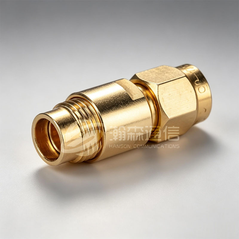
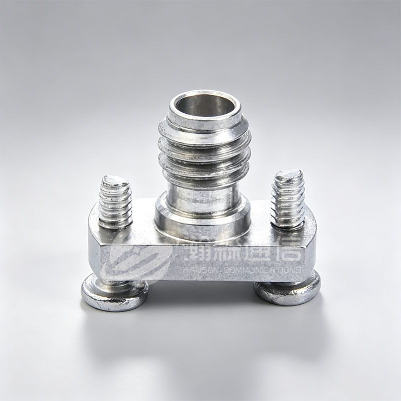
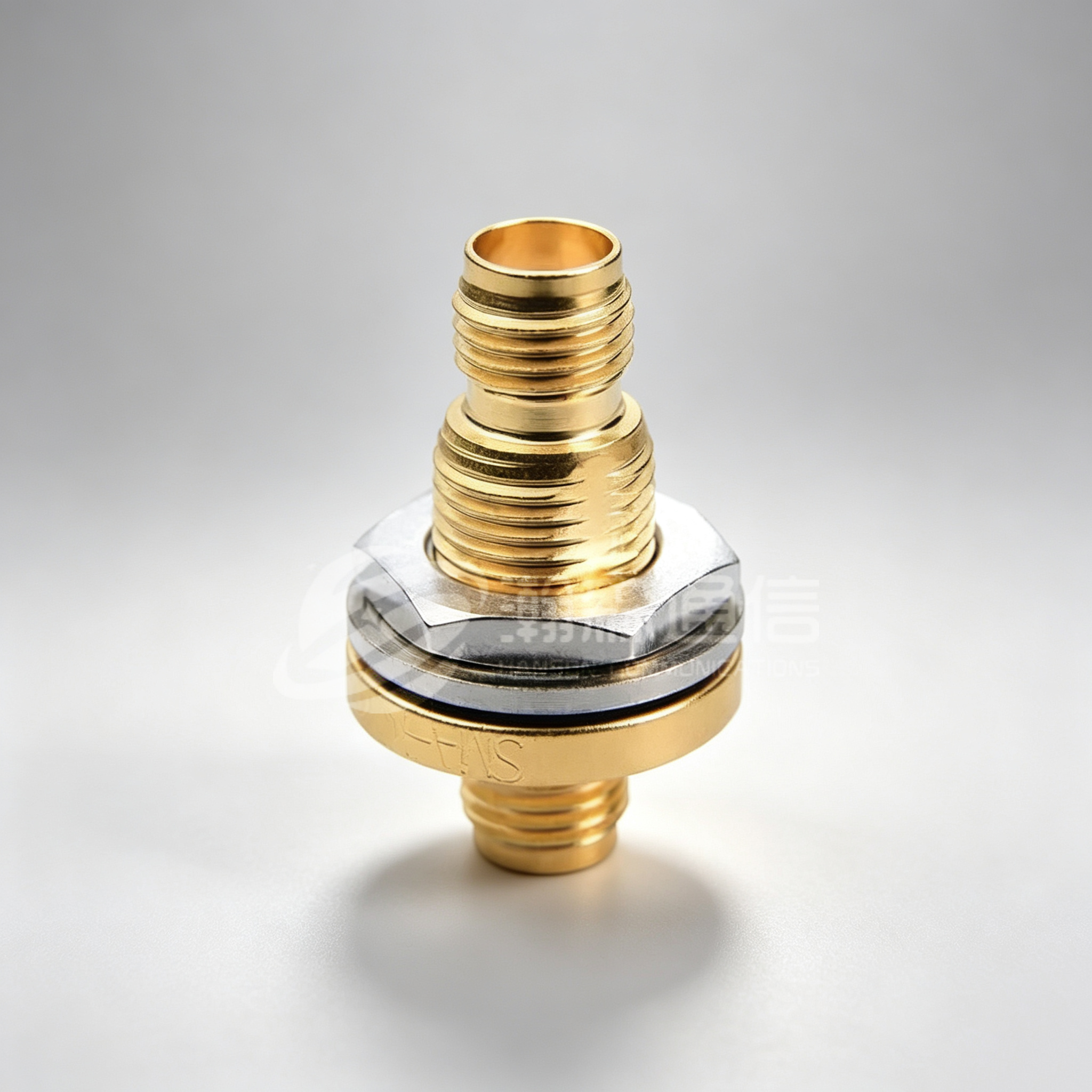
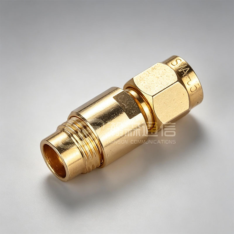 Custom SMA RF Coaxial Connector Supplier, CompanyNingbo Hanson Communication Technology Co., Ltd. is a professional China SMA RF coaxial connectors supplier and SMA connector company, we...View Product →
Content
- 1 Start with the Basic Construction: What You Are Actually Selecting
- 2 Impedance: The 50-ohm vs. 75-ohm Decision
- 3 Frequency Range and the Role of Dielectric Loss
- 4 Attenuation: How to Read the Spec Sheet
- 5 Common Coaxial Cable Types: Which One Fits Your Run?
- 6 Shielding: The Second-Order Effect That Becomes First-Order in Dense Environments
- 7 Connectors: The Point Where a Cable Is Won or Lost
- 8 Flexibility, Bend Radius, and Installation
- 9 Rain, Temperature, and Ultraviolet Exposure
- 10 Data Visualization: Comparing Numbers at a Glance
- 11 Matching Cable to Connector: A Practical Checklist
- 12 How to Read a Coaxial Cable Label
- 13 Buying New vs. Continuing with an Existing Cable: What to Check
- 14 The Cost of a Wrong Choice
- 15 Coaxial Cable Selection Guide: The 5-Step Process
- 16 Frequently Asked Questions
Start with the Basic Construction: What You Are Actually Selecting
A coaxial cable has four concentric layers: an inner conductor, a dielectric insulator, a shield, and an outer jacket. Each layer affects electrical performance differently. The inner conductor can be solid copper, copper-clad steel, or stranded copper. Solid conductors offer lower DC resistance and better phase stability; stranded conductors provide flexibility but add insertion loss. The dielectric should be solid polyethylene (PE), foam PE, or polytetrafluoroethylene (PTFE). Foam dielectrics trap air, reducing dielectric constant and attenuation, which makes them the default for low-loss cables. PTFE handles higher temperatures but costs more and has slightly higher loss than foam PE. The shield can be a single braid, double braid, or foil-and-braid combination. Shielding effectiveness is measured in dB of isolation from external interference, and a double-shielded cable typically delivers 10 to 20 dB better screening than a single-braid equivalent.
Impedance: The 50-ohm vs. 75-ohm Decision
Impedance is the first filter in cable selection. The RF industry standard is 50 ohms for transmitters, receivers, antennas, and test instruments. It represents a compromise between minimum attenuation and maximum power handling. Video and broadcast systems use 75 ohms because that impedance produces lower attenuation at high frequencies when the dielectric outer diameter is fixed. Most selection guides simplify this to "50 for RF, 75 for video," but there is an important nuance. If you use a 75-ohm cable in a 50-ohm system, the voltage standing wave ratio rises to roughly 1.5:1, causing about 4 percent of power to be reflected. For sensitive receiver inputs that reflection can be acceptable; for transmitter outputs it can overheat the final amplifier stage. When in doubt, match the cable impedance to the system impedance and avoid impedance-matching adapters unless the mismatch is intentional and calculated.
Frequency Range and the Role of Dielectric Loss
Every coaxial cable has a usable frequency ceiling. Above that ceiling, the dielectric becomes lossy, and the cable starts to behave more like a waveguide than a transmission line. Semi-rigid cables with solid PTFE and a solid outer conductor can reach 40 GHz or higher in small diameters. Flexible cables with braided shields and foam PE dielectrics typically stay below 6 GHz unless they use specialized low-loss materials. The dielectric constant determines the velocity factor: solid PE gives a velocity factor of about 0.66, foam PE around 0.80 to 0.88, and air-spaced designs up to 0.96. A higher velocity factor means shorter electrical delays and lower loss per meter at the same frequency. For a 3-meter cable run at 3.5 GHz, the difference between a foam PE dielectric and solid PE can be 0.4 to 0.6 dB of loss, which is enough to affect the margin in a fixed link budget.
Attenuation: How to Read the Spec Sheet
Attenuation is usually specified in dB per 100 meters at a given frequency, and the curve follows an approximate square-root relationship with frequency. A cable with 10 dB loss at 1 GHz will show about 22 dB loss at 5 GHz, assuming the same construction. That means the "average loss" figure is meaningless unless the frequency is identified. A quick way to compare cables is to look at the attenuation per 100 meters at 2.4 GHz or 5 GHz, depending on your target band. For example, RG-58 shows around 25 dB per 100 meters at 2.4 GHz, LMR-400 around 4 dB per 100 meters at 2.4 GHz, and a 1/2-inch corrugated cable around 2 dB. The trade-off is thickness and bend radius: the lower-loss cable is physically bigger and cannot be bent as tightly. When you plan a cable run, calculate the total loss by adding the attenuation per meter multiplied by the length, plus connector losses. Every connector pair adds 0.1 to 0.3 dB loss on average, so a run with four connector pairs loses 0.8 to 1.2 dB before the cable itself is counted.
Common Coaxial Cable Types: Which One Fits Your Run?
The RG designation system is older than most engineers realize, and it does not guarantee cross-manufacturer consistency. That being said, the common RG types remain useful shorthand for sizing and performance expectations.
RG-58 and RG-174: Thin, Flexible, and Lossy
RG-58 (about 5 mm diameter) and RG-174 (about 2.8 mm diameter) are both 50-ohm cables with solid or stranded center conductors. RG-58 is suitable for short indoor jumper cables up to 1 GHz, where the run is under 2 meters. RG-174 has roughly double the attenuation of RG-58 at the same frequency and is intended only for very short pigtails inside an enclosure. If your application requires a long run that can survive repeated flexing, neither cable is appropriate.
RG-59 and RG-6: 75-ohm Basics for Video and CATV
RG-59 (about 6.2 mm diameter) and RG-6 (about 6.9 mm diameter) are 75-ohm cables. RG-6 has a thicker dielectric and lower loss, making it the dominant choice for CATV drop lines, cable modems, and HDTV antennas. RG-59 is still seen in older CCTV installations and composite video lines. For modern HD-SDI video at 1080p, RG-6 is the minimum acceptable cable for runs beyond 30 meters; RG-59 will start showing pixelation or sync issues.
LMR-Type (or Equivalent) Low-Loss Flexible Cables
LMR-400 and its equivalents use a solid or stranded center conductor, a foam PE dielectric, and a combination of foil and braid shields. The result is attenuation close to a 1/2-inch semi-rigid cable at a fraction of the weight, with a bend radius of about 25 mm. This cable family is the standard for Wi-Fi antenna feeds, cellular donor antennas, and two-way radio systems where the run exceeds 10 meters. The term "LMR" is a brand name, but many manufacturers offer electrically similar cables; always check the spec sheet for the exact velocity factor and shield transfer impedance.
Semi-Rigid and Super-Low-Loss Assemblies
Semi-rigid cables use a solid copper outer conductor and solid PTFE dielectric. Once bent into shape, they do not move, which makes them ideal for phase-critical applications like military radar feed networks. The trade-off is that bending requires special tools and the cable cannot be re-bent multiple times. For applications that need both low loss and field flexibility, manufacturers now offer super-low-loss flexible cable assemblies that use a corrugated or braided outer conductor with a low-density PTFE dielectric. These cables achieve near-semi-rigid loss numbers while surviving repeated flexing at the connector interface.
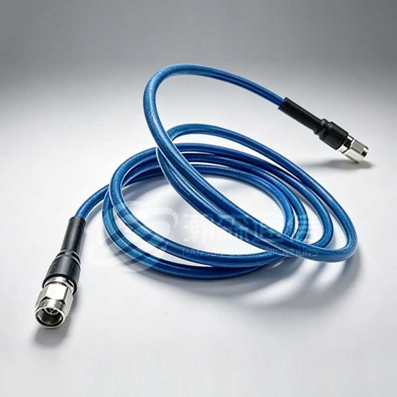 Custom Super Low-Loss Flexible Cable Assembly Supplier, CompanyNingbo Hanson Communication Technology Co., Ltd is China Super Low-Loss Flexible Cable Assembly supplier and company, offer custom soluti...View Product →
Shielding: The Second-Order Effect That Becomes First-Order in Dense Environments
Shielding effectiveness is not stated as a single-frequency number in most datasheets. The standard practice is to test transfer impedance over a frequency range. A good braided shield has a transfer impedance of 1 to 5 milliohms per meter below 100 MHz, rising to 50 to 200 milliohms per meter by 1 GHz. A foil-and-braid combination can hold transfer impedance below 5 milliohms per meter up to several gigahertz. Inside a crowded radio room, where multiple transmitters operate with outputs of tens of watts, a poorly shielded cable acts as an unintentional antenna. The result is desensitization of receivers, intermodulation products, and audio buzz in low-frequency circuits. The shielding rule of thumb: if the cable runs outdoors, parallel to other cables, or within 1 meter of high-power radios, choose a double-shielded type and verify the shield coverage percentage ( braided shields on good-quality cables are 90 to 97 percent).
Connectors: The Point Where a Cable Is Won or Lost
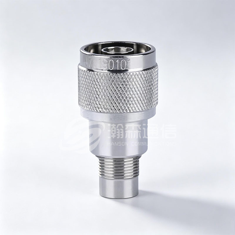
A cable is only as good as its connectors. An N-type connector handles up to 11 GHz (some precision versions to 18 GHz) and offers weather resistance when clamped or crimped to the cable. SMA connectors are physically smaller and work to 18 GHz (or 27 GHz in some variants), but they require precise center-pin alignment and a torque wrench at 0.56 N·m; overtightening by hand can crack the dielectric and cause intermittent shorts. When you choose a connector, consider what happens at the cable-to-connector junction:
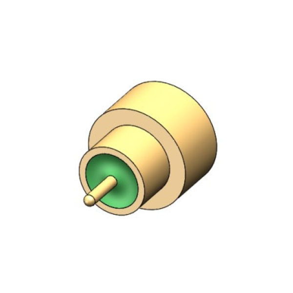
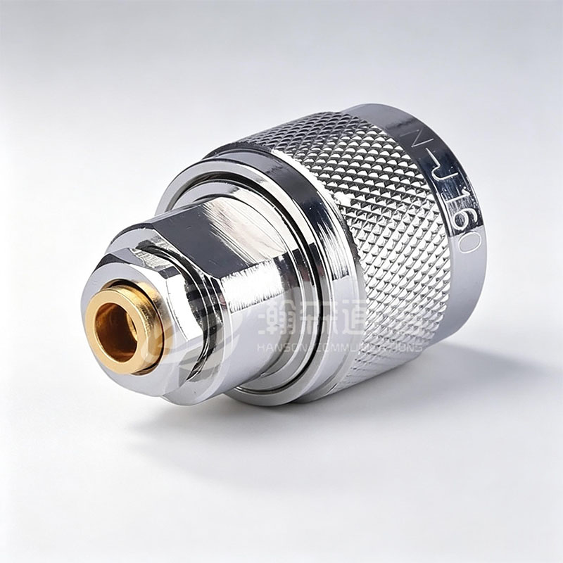 Custom N type RF Coaxial Connector Supplier, CompanyNingbo Hanson Communication Technology Co., Ltd. is a professional China custom N type RF coaxial connector supplier and company, we offe...View Product →
- Crimp connectors: fast, repeatable, and require a calibrated crimp tool for the specific cable diameter.
- Clamp connectors: hold the cable jacket with a compression ring, tolerate slight diameter variations.
- Solder-type connectors: give the best electrical contact but are slow to assemble and risk overheating the dielectric.
If you are ordering pre-made cable assemblies, the attachment method is the manufacturer’s responsibility, but the spec sheet should state the cable type, the connector torque, and the tested VSWR over the operating frequency range. A VSWR above 1.5:1 for a small connector like SMA is a red flag in modern RF design; most precision assemblies hold VSWR below 1.3:1.
Flexibility, Bend Radius, and Installation
Data sheets usually list a minimum bend radius for one-time installation and a larger radius for repeated flexing. Exceeding the minimum bend radius can cause a compressed shield and a local impedance bump that shows up as a VSWR spike at certain frequencies. For permanent installations, the rule is to leave at least 2 to 3 times the listed bend radius as a safety margin. If the cable must flex during operation, choose a stranded-center-conductor cable and verify the flex life in cycles. Many low-loss flexible cables will survive 1,000 to 5,000 flex cycles when the bend radius stays within spec. A semi-rigid cable may crack after just a few cycles.
Rain, Temperature, and Ultraviolet Exposure
Outdoor cables need more than a plastic jacket. The outer jacket should be UV-stabilized polyethylene or a similar weather-resistant material. PVC jackets are cheaper but crack under prolonged sunlight and stiffen at temperatures below freezing. When a cable passes through an outdoor wall, use a drip loop and seal the cable entry point with weatherproof putty; otherwise, water migrates along the braid and corrodes the shield. Consider also the temperature rating of the dielectric. Standard PE stays usable down to -40°C, but the jacket becomes brittle. PTFE cables handle up to 200°C, which is why they appear in high-power transmit circuits near hot amplifier components. For an installation that mixes indoor and outdoor sections, a cable with a polyolefin jacket or a PE jacket over a foil-and-braid shield is a safe middle ground.
Data Visualization: Comparing Numbers at a Glance
The physics becomes clearer when you visualize it. The following charts compare typical performance for the cable families discussed. The values are representative figures from published datasheets, not a substitute for a specific supplier’s spec sheet.
Attenuation Comparison at 2.4 GHz
Shielding Effectiveness Comparison
Dielectric and Velocity Factor
Matching Cable to Connector: A Practical Checklist
A cable selection guide would be incomplete without connecting cable choice to connector series. The connector pins have a defined center conductor diameter range, and using a cable with a thinner center pin than the connector expects causes a poor solder joint or a loose crimp. A cable with a thicker center conductor than the connector allows can deform the connector body and create a mismatch. The common pairings are:
| Connector Type | Matching Cable Examples | Typical Use |
|---|---|---|
| SMA | RG-174, RG-316, LMR-100, semi-rigid 0.141" | Wi-Fi radios, test points, GPS antennas |
| N-type | RG-213, LMR-400, RG-8 | Base stations, outdoor antennas, high-power transmitters |
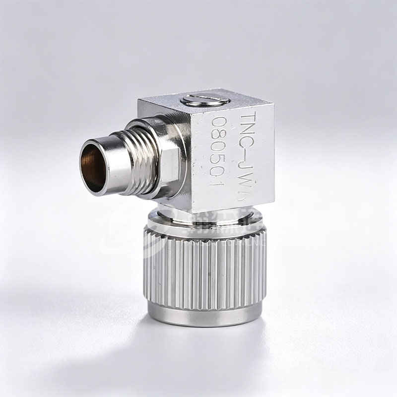
| TNC | RG-58, RG-142, LMR-240 | Mobile radio, PTP links, vibration-prone installs |
| BNC | RG-58, RG-59, RG-71 | Test equipment, video surveillance, 10Base-2 networks |
How to Read a Coaxial Cable Label
Cable labels are inconsistent across manufacturers. Some print the UL style number, some print the RG designation, and some print a proprietary model name. The critical information that should appear is the impedance, the capacitance in pF/m, the outside diameter, and the frequency range. If a cable label shows only "RG-6" and a brand name, treat it as an incomplete spec. The capacitance for a 50-ohm cable is typically 80 to 100 pF/m, while a 75-ohm cable is 65 to 70 pF/m. If capacitance is missing, measure it: a capacitance meter across a 1-meter sample gives you the approximate impedance by using the formula Z0 = 1/(c*C), where c is the velocity factor and C is capacitance per meter. This is a useful field verification method when dealing with unmarked surplus cable.
Buying New vs. Continuing with an Existing Cable: What to Check
If you are replacing a failed cable in an existing system, pull the old cable and inspect the end before ordering a substitute. A cable that was crushed by a clamp, pulled beyond its bend radius, or exposed to moisture will not recover just because you re-crimp the connector. Look at the shield condition: if the braid is darkened or green, corrosion has already increased its resistance and the cable should be decommissioned. If the dielectric is discolored, thermal damage has raised its loss. In those cases, re-using the same cable type with the same length is reasonable, but upgrading to a double-shielded version at a slightly larger diameter often solves recurring interference problems without changing the connector scheme.
The Cost of a Wrong Choice
Consider the total installed cost, not just the price per meter of cable. A 20-meter run using RG-58 costs about $30 in cable plus $10 in connectors. An equivalent LMR-400 run costs $90 in cable and $15 in connectors. But if the RG-58 run has an extra 4 dB of loss, lowering the received signal by 4 dB, that could require a $200 amplifier at the far end to compensate. The cheaper cable is only cheaper until you add the amplifier. The same logic applies to shielding. A double-shielded cable costs 30 to 50 percent more than a single-shielded type, but in an environment with a nearby transmitter, the double-shielded cable avoids intermittent issues that waste days of troubleshooting.
Coaxial Cable Selection Guide: The 5-Step Process
- List the system requirements: impedance, frequency range, maximum insertion loss, and operating environment.
- Calculate the link budget: total cable length, connector count, and expected signal levels at both ends.
- Shortlist cable types that meet the loss budget and physical clearance constraints.
- Evaluate shielding needs based on proximity to interference sources and outdoor exposure.
- Confirm connector compatibility and decide on factory-terminated vs. field-terminated options.
For a standardized approach, many procurement engineers keep a small set of approved cable types: one flexible RG-type for short jumpers, one low-loss flexible for antenna feeds, and one semi-rigid or super-low-loss type for high-frequency or high-reliability paths. This limits inventory and ensures the field team is comfortable with the termination method.
Frequently Asked Questions
What is the difference between RG-6 and RG-59 coaxial cable?
RG-6 has a thicker dielectric, lower attenuation, and a larger diameter. It is the standard for HD video and cable internet. RG-59 is thinner and used for shorter analog video runs or legacy CCTV. For modern high-frequency signals, choose RG-6.
Can I use a 75-ohm cable instead of a 50-ohm cable?
Technically yes, but a 75-ohm cable in a 50-ohm system creates a 1.5:1 VSWR, causing reflected power. For receivers this may be acceptable, but for transmitters it can damage the amplifier. Always match the system impedance.
What does attenuation mean in coaxial cable specs?
Attenuation is the reduction in signal amplitude as it travels through the cable, measured in dB per 100 meters at a specified frequency. Lower attenuation means better signal strength at the far end. Attenuation increases with frequency.
How long can a coaxial cable run be before signal loss becomes a problem?
It depends on cable type and frequency. An LMR-400 run at 2.4 GHz can go 50 to 80 meters with less than 3 dB loss, while an RG-58 run at the same frequency exceeds 3 dB loss at just 12 meters. Calculate your link budget first.
Are higher-quality coaxial cables worth the extra cost?
When the link budget is tight or the environment has high interference, a better cable with lower loss and better shielding avoids adding an amplifier or repeater. A $50 cable upgrade is cheaper than a $300 amplifier and more reliable.
How do I know which coaxial cable connector type I need?
Check the ports on your equipment. Common RF connectors include SMA (small, up to 18 GHz), N-type (weatherproof, up to 11 GHz), BNC (quick connect, up to 4 GHz), and TNC (threaded BNC, up to 11 GHz). Match the connector to the port and the cable impedance.

Looking For Business Opportunity?
Request for a call today
-

+86-15715730755
-

-

No. 1, Longcao Road, Dongqian Lake Tourism Resort Industrial Zone, Yinzhou District, Ningbo City, Zhejiang, China.
Message
Copyright © Ningbo Hanson Communication Technology Co., Ltd.
