


 English
 русский
Industry News
 Home / News / Industry News / RF Connector Types Chart: How to Identify and Select the Right RF Connector
 RF Connector Types Chart: How to Identify and Select the Right RF Connector
 2026.09.16
 Industry News
The prototype is finally on the bench, and then the reminder arrives: the board's SMA port has to meet a test cable that ends in BNC, while the roof antenna uses an N-type bulkhead. None of the three will mate directly, and the adapter you grab becomes the weakest part of the measurement path.
An RF connector types chart is the fastest way to avoid that scene. It condenses interface geometry, frequency limit, impedance and coupling style into one reference view. This article explains what the chart says about the connectors you will meet most often, how to identify them at a glance, and which selection rules separate a stable link from a field failure.
Content
- 1 Why a Connector Chart Is the First Design Filter
- 2 RF Connector Types Chart: Core Families at a Glance
- 3 Frequency Limits: The Chart That Saves the Most Redesigns
- 4 Identification: Gender, Polarity and Coupling
- 5 Impedance and Adapter Compatibility
- 6 How to Choose the Right RF Connector for Your Application
- 7 Common Mistakes When Selecting RF Connectors
- 8 RF Connector Types: Frequently Asked Questions
Why a Connector Chart Is the First Design Filter
Leading with the conclusion: every RF connector is a mechanical interface with an electrical limit. Exceed the frequency rating, and the internal geometry stops behaving like a clean transmission line, so reflections and leakage climb. Mismatch the impedance, and part of the signal bounces back toward the source instead of reaching the load. Pick a coupling style that does not suit the vibration environment, and the link becomes intermittent.
A chart turns those three constraints into a shortlist before you order samples. The columns you should read are:
- Frequency rating — the maximum usable range before VSWR and leakage degrade; always leave margin below this value.
- Impedance — 50Ω for most telecom, wireless and test paths; 75Ω for video and broadcast distribution.
- Mechanics — coupling method, body size, mating cycles, sealing and the torque recommended for installation.
If the vocabulary around these columns is still new, the RF coaxial connector basics provide a useful starting point before you apply the chart.
RF Connector Types Chart: Core Families at a Glance
The table below groups the interfaces you will encounter in modules, test benches, base stations and cable assemblies. Ratings follow the IEC 60169 series and IEEE 287 precision-connector specifications; premium test-grade versions of several families extend the limits further.
| Connector type | Impedance | Coupling | Typical max frequency | Common applications | Notes |
|---|---|---|---|---|---|
| BNC | 50Ω (75Ω versions exist) | Bayonet | 4 GHz | Test instruments, video routing, legacy radio gear | Quick connect/disconnect; not for strong vibration |
| SMA | 50Ω | Threaded | 18 GHz | Module-to-cable links, antennas, instrumentation | Compact; RP-SMA variant used in Wi-Fi and cellular |
| TNC | 50Ω | Threaded | 11 GHz | Outdoor radios, vibration-prone environments | BNC-sized shell with threaded coupling |
| N | 50Ω | Threaded | 11 GHz standard / 18 GHz precision | Base stations, outdoor antennas, broadcast transmitters | Weather-resistant, constant 50Ω across the band |
| 2.4 mm | 50Ω | Threaded | 50 GHz | 5G FR2 and millimetre-wave test | Precision interface for mmWave laboratories |
| 1.85 mm | 50Ω | Threaded | 67 GHz | High-speed digital, V- and E-band modules | Precision family used in large test systems |
| 1.0 mm | 50Ω | Threaded | 110 GHz | Advanced metrology and mmWave instruments | Smallest precision interface commonly available |
| UHF | 50Ω nominal (non-constant) | Threaded | 300 MHz | Legacy two-way radio and CB gear | PL-259/SO-239 style; impedance not constant |
| MCX / MMCX | 50Ω / 75Ω | Snap-on | 6 GHz | GPS, IoT modules, internal antenna links | Sub-miniature and push-on, suited to dense PCBs |
Frequency Limits: The Chart That Saves the Most Redesigns
The most common reason a connector choice fails in a prototype is simple: the operating frequency crosses the interface rating. Above that rating, the connector no longer behaves as part of a controlled impedance line, and higher-order modes begin to appear. The chart below shows where the mainstream families stop.
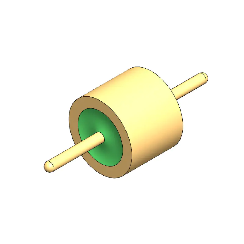
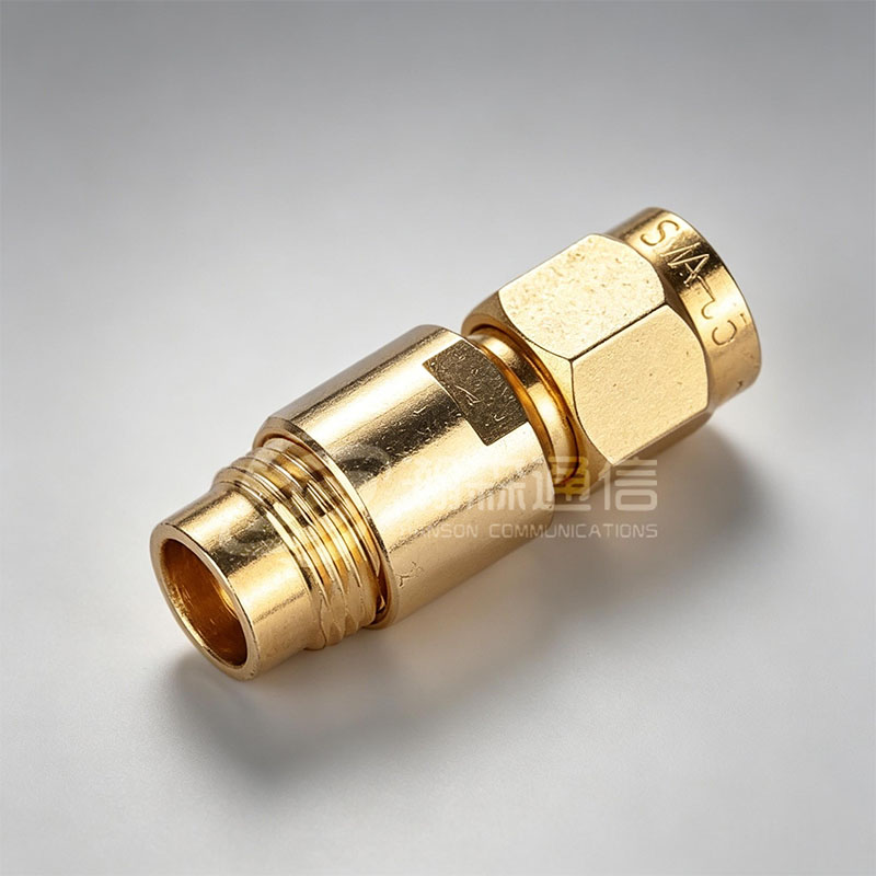 SMA RF Coaxial Connector for Compact Board-to-Cable LinksSMA offers a threaded 50Ω interface rated DC–26.5 GHz, making it the default choice for compact modules. Its small size and stable performance suit microwave communications and measurement systems.View Product →
Three observations make this chart easy to use. First, BNC belongs on the bench: below 4 GHz it is convenient and inexpensive, above 4 GHz it reflects and leaks. Second, SMA covers essentially every compact board-to-cable application up to 18 GHz, which is why module designers default to it. Third, N and TNC both handle 11 GHz with constant 50Ω impedance, but N is preferred outdoors for its weather resistance, while TNC offers the smaller BNC body with threaded stability.
For a compact board-to-cable interconnect up to 18 GHz, the SMA family remains the practical default, and a well-machined SMA interface keeps the transition low-loss through the full rated band.
Identification: Gender, Polarity and Coupling
Two connectors from the same family can still refuse to mate if the gender or polarity differs. Check these three details first:
- Gender — a plug (male) carries a centre pin; a jack (female) carries a centre socket.
- Polarity — standard polarity places the pin on the plug; reverse polarity (RP) swaps the centre contact to the jack. RP types are common on Wi-Fi and cellular equipment to prevent accidental mating.
- Coupling — threaded (SMA, TNC, N), bayonet (BNC), or snap-on (MCX, MMCX). The locking style is a direct clue to the vibration level the designer expected.
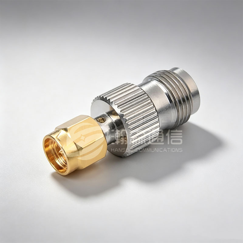
A fast field check: BNC has two bayonet studs in its slots, TNC looks like BNC but is threaded, SMA is small with a 1/4-inch hex nut, and N is the largest of the four with a 5/8-inch hex nut. Measuring the hex and studying the locking style resolves most identification questions without a catalogue.
Impedance and Adapter Compatibility
After frequency and coupling, impedance is the third hard filter. Keep 50Ω for cellular, Wi-Fi, GPS, radar and most instrumentation; keep 75Ω for video and broadcast distribution. A 50Ω BNC and a 75Ω BNC will physically mate, but the mismatch produces reflections that show up as ripple across the passband. One impedance, end to end, is the rule.
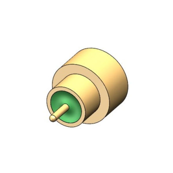
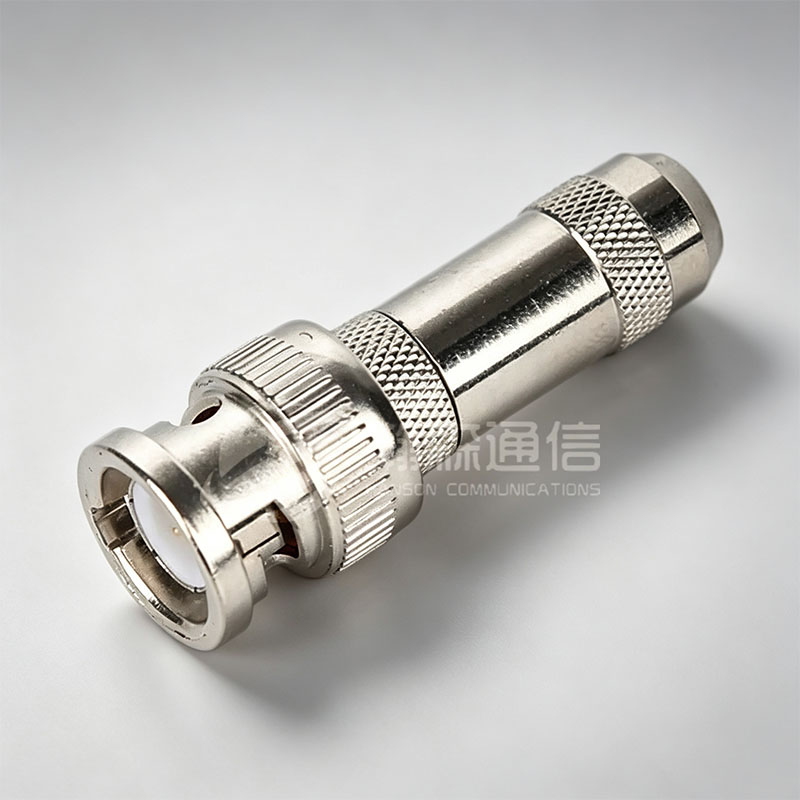 BNC RF Connector for Laboratory and Broadcast UseBNC provides quick bayonet coupling for reliable connections up to 4 GHz at 50Ω. Its ease of use and availability make it a workhorse for instruments and broadcast applications.View Product →
BNC is still the workhorse of laboratory instruments and broadcast rooms. For stable measurements up to 4 GHz, a dependable BNC interface keeps repeatability high and replacements simple.
When different sections of a system use different families — SMA on the board, N on the antenna, TNC on a jumper — standardised adapters make the conversion straightforward. Keep the adapter close to the measurement reference plane and avoid stacking several in series, because every extra transition adds VSWR. The practical criteria for picking one are covered in our guide to choosing the right RF coaxial adapter.
How to Choose the Right RF Connector for Your Application
Work through the list below in order, and the connector family narrows itself down.
- Frequency first: select a family whose rating sits above your highest operating frequency, with margin. Interfaces operating at the edge of the rating degrade with age and temperature.
- Mechanical environment: threaded coupling for vibration and outdoor use, bayonet when you connect and disconnect often, snap-on for dense PCBs and low assembly effort.
- Impedance: match the system impedance exactly. For most RF work that means 50Ω.
- Size and footprint: check panel space, bend radius of the attached cable, torque access for mating, and the mating cycles expected.
- Supply and servicing: standard families give you multiple sources and field spares; it is worth avoiding proprietary interfaces in long-life equipment.
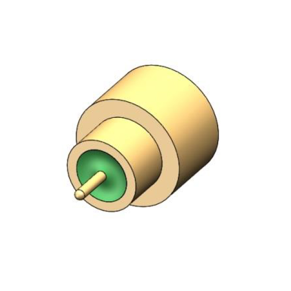
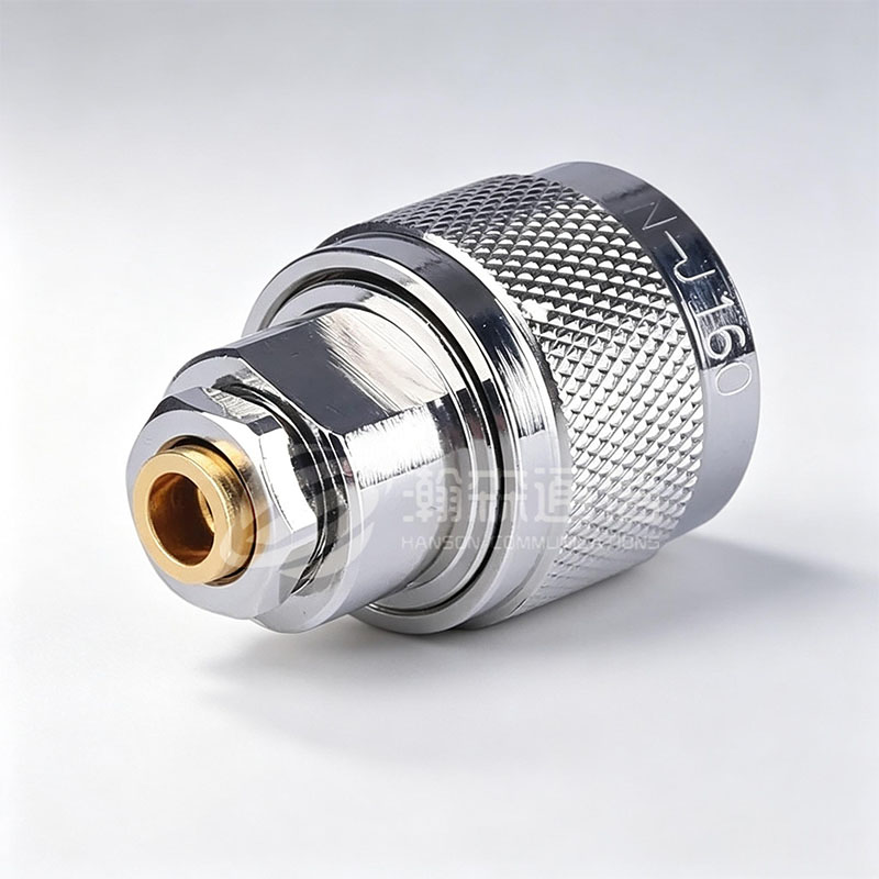 N-type RF Coaxial Connector for Outdoor InfrastructureN-type connectors deliver threaded stability, weather resistance, and 50Ω impedance up to 18 GHz. Recommended for base stations and antennas, they handle higher power and outdoor environments well.View Product →
For outdoor base stations and antennas, we typically recommend N-type first: it is weather-resistant, handles higher power, and holds a constant 50Ω impedance through its rated band. It is the interface most often specified for infrastructure links.
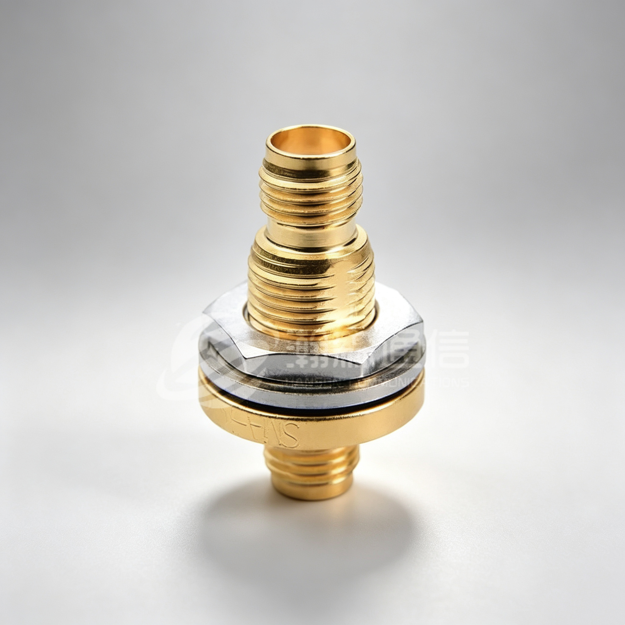
One extra consideration: if the installation crosses a pressure barrier, high humidity, or a sealed enclosure, a hermetically sealed connector with a glass insulator should be on the shortlist, because moisture ingress changes long-term reliability far more than the initial VSWR figure suggests.
Common Mistakes When Selecting RF Connectors
- Running BNC beyond 4 GHz. The bayonet joint leaks and reflects; the bench is its comfort zone.
- Ignoring reverse polarity. A standard SMA plug and an RP-SMA plug look almost identical, but one of them will not mate with its counterpart.
- Mixing 50Ω and 75Ω in the same path. Physically compatible connectors can still create reflections that reduce link quality.
- Choosing a family with no frequency margin. Operating right at the published maximum leaves no headroom for cable, adapter and production tolerances.
- Underweighting installation quality. Torque, centre-pin seating and crimp consistency matter as much as the connector type; a good interface installed badly fails quickly.
RF Connector Types: Frequently Asked Questions
What is the most common RF connector type?
SMA is the most common connector in module-level radio and instrumentation designs, while BNC dominates test bench and legacy broadcast equipment. For outdoor infrastructure, N-type is the usual choice.
What is the difference between SMA and BNC?
SMA is a threaded, compact connector rated to 18 GHz; BNC uses a bayonet lock, is easier to connect and disconnect, and is rated to about 4 GHz.
What frequency does an N-type connector support?
Standard N-type connectors are rated to 11 GHz, while precision versions reach 18 GHz. It is a constant-impedance 50Ω interface widely used outdoors.
What does RP-SMA mean?
RP stands for reverse polarity: the plug carries a centre socket instead of a centre pin. Standard and reverse-polarity SMA connectors will not mate, which prevents accidental use.
Can 50Ω and 75Ω connectors be mixed?
Some families, such as BNC, exist in both impedances and can physically mate. The impedance mismatch creates reflection and attenuation, so mixing is acceptable only where loss can be tolerated.
How can I identify an RF connector by appearance?
Check the locking style and size first: BNC has bayonet slots, TNC is threaded with a BNC-sized body, SMA is small with a 1/4-inch hex nut, and N is the large threaded type with a 5/8-inch nut.

Looking For Business Opportunity?
Request for a call today
-

+86-15715730755
-

-

No. 1, Longcao Road, Dongqian Lake Tourism Resort Industrial Zone, Yinzhou District, Ningbo City, Zhejiang, China.
Message
Copyright © Ningbo Hanson Communication Technology Co., Ltd.
