


 English
 русский
Industry News
 Home / News / Industry News / VSWR to Return Loss Conversion: Formula, Chart & Practical Guide for RF Engineers
 VSWR to Return Loss Conversion: Formula, Chart & Practical Guide for RF Engineers
 2026.09.23
 Industry News
If you work with RF systems, you already know that VSWR (Voltage Standing Wave Ratio) and return loss are two sides of the same coin. Both measure the same physical phenomenon — the amount of signal reflected back due to impedance mismatches in a transmission line. The key difference is the scale: VSWR is a linear ratio (e.g., 1.5:1), while return loss is expressed in decibels (e.g., 14 dB). Once you understand the math, converting between them becomes straightforward. This article gives you the exact formula, a handy conversion table, visual charts, and practical advice on how to improve these critical parameters in your system.
Content
- 1 What Are VSWR and Return Loss?
- 2 VSWR to Return Loss Conversion Formula
- 3 VSWR to Return Loss Conversion Table
- 4 Visualizing the Relationship: VSWR vs. Return Loss
- 5 Why VSWR and Return Loss Matter in RF Systems
- 6 How to Improve VSWR and Return Loss in Practice
- 7 Isometric Illustration: Standing Wave Pattern
- 8 Frequently Asked Questions About VSWR and Return Loss
What Are VSWR and Return Loss?
VSWR quantifies the ratio of the maximum voltage to the minimum voltage along a transmission line. A perfect match gives a VSWR of 1:1 (no reflected power). As the mismatch increases, VSWR rises. Return loss, on the other hand, tells you how much of the forward power is reflected back toward the source, measured in dB. A higher return loss means less reflected power and a better match.
The two are mathematically linked by the reflection coefficient (Γ):
Γ = (VSWR – 1) / (VSWR + 1)
Return Loss (dB) = –20 log₁₀(Γ)
So, a VSWR of 1.5:1 corresponds to a reflection coefficient of 0.2 and a return loss of about 14 dB.
VSWR to Return Loss Conversion Formula
To convert from VSWR to return loss, plug the VSWR value into these steps:
- Compute Γ = (VSWR – 1) / (VSWR + 1)
- Return Loss (dB) = –20 × log₁₀(Γ)
For example, VSWR = 2.0 → Γ = (2-1)/(2+1) = 0.333 → Return Loss = –20 × log₁₀(0.333) ≈ 9.54 dB.
To go the other way (return loss to VSWR):
- Γ = 10^(–Return Loss / 20)
- VSWR = (1 + Γ) / (1 – Γ)
VSWR to Return Loss Conversion Table
| VSWR | Return Loss (dB) | Reflection Coefficient | Reflected Power (%) |
|---|---|---|---|
| 1.00 | ∞ | 0.000 | 0.00 |
| 1.10 | 26.44 | 0.048 | 0.23 |
| 1.20 | 20.83 | 0.091 | 0.83 |
| 1.30 | 17.69 | 0.130 | 1.70 |
| 1.40 | 15.56 | 0.167 | 2.78 |
| 1.50 | 13.98 | 0.200 | 4.00 |
| 1.60 | 12.74 | 0.231 | 5.33 |
| 1.70 | 11.73 | 0.259 | 6.72 |
| 1.80 | 10.88 | 0.286 | 8.16 |
| 1.90 | 10.16 | 0.310 | 9.63 |
| 2.00 | 9.54 | 0.333 | 11.11 |
| 2.50 | 7.36 | 0.429 | 18.37 |
| 3.00 | 6.02 | 0.500 | 25.00 |
Visualizing the Relationship: VSWR vs. Return Loss
The chart below shows how return loss decreases as VSWR increases. The curve is steep in the low-VSWR region, meaning a small improvement in VSWR (e.g., from 1.5 to 1.3) yields a large improvement in return loss.
Why VSWR and Return Loss Matter in RF Systems
When VSWR is high (or return loss low), a significant portion of the transmitted power is reflected back to the source. This leads to:
- Reduced radiated power – Less energy reaches the antenna.
- Possible damage – Reflected power can overheat power amplifiers.
- Signal distortion – Standing waves cause phase and amplitude errors.
Industry standards vary by application: for cellular base stations, a return loss of 20 dB (VSWR ≈ 1.22) is typical, while consumer Wi-Fi systems may accept 10 dB (VSWR ≈ 1.92).
How to Improve VSWR and Return Loss in Practice
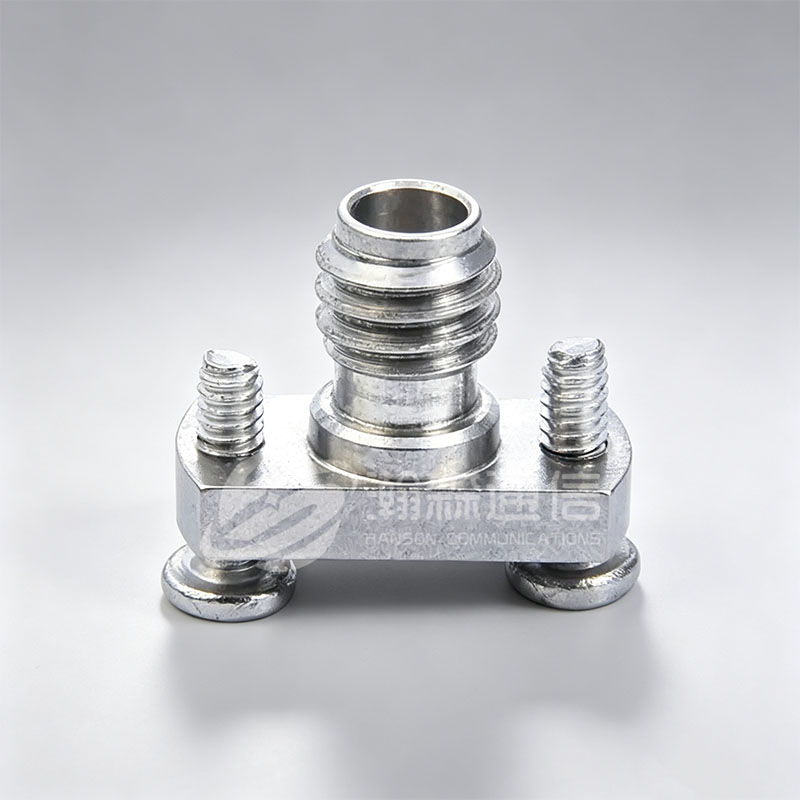
Improving these metrics starts at the component level. Using precision-engineered connectors, adapters, and cables with well-controlled impedance reduces reflections at every interface. For example, replacing a generic N-type connector with a high-quality version can improve return loss by several dB in the 2–6 GHz range.
Here are three actionable steps:
- Choose components rated for your frequency band – Not all connectors perform equally at higher frequencies. A connector specified up to 18 GHz will have tighter tolerances than one rated at 6 GHz.
- Ensure proper installation – Torque, center pin depth, and cleanliness directly affect VSWR. Even a small gap can create an impedance bump.
- Use low-loss, flexible cable assemblies – Cable bending and quality matter. Super low-loss assemblies help maintain consistent impedance through the run.
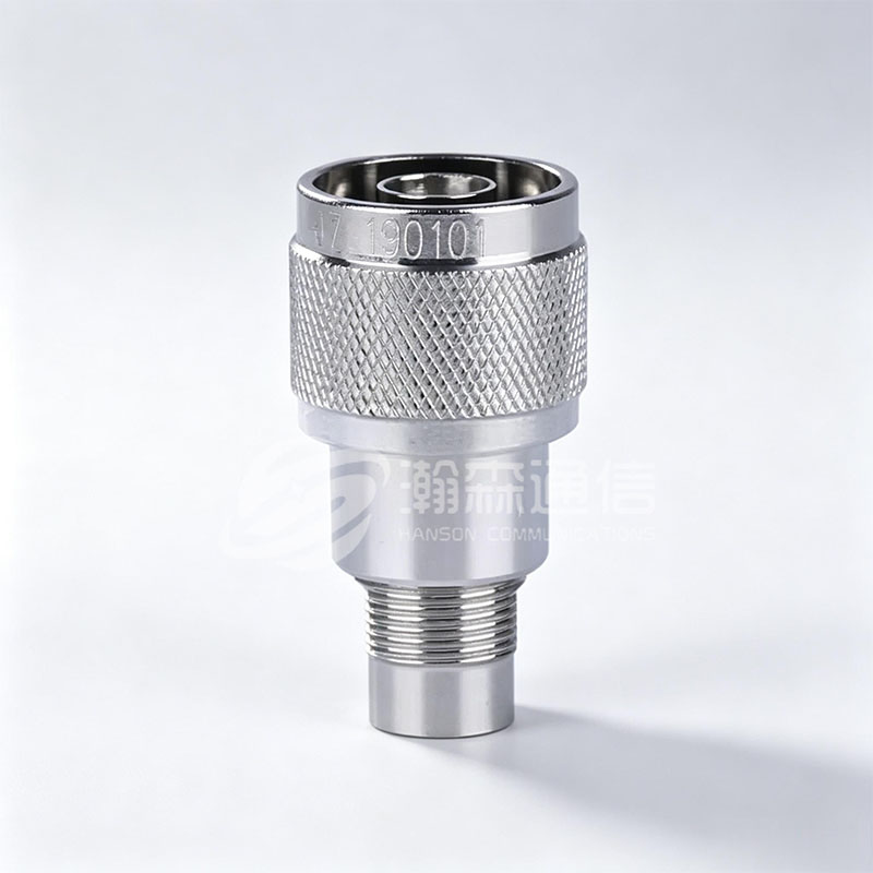
When upgrading your system, consider using 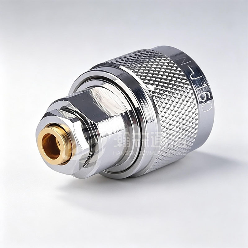 N-type RF Coaxial Connector for Outdoor ConnectionsThis threaded connector offers wide bandwidth, shock resistance, and low VSWR, making it a reliable choice for rugged outdoor links and system upgrades.View Product → for rugged outdoor connections, combined with
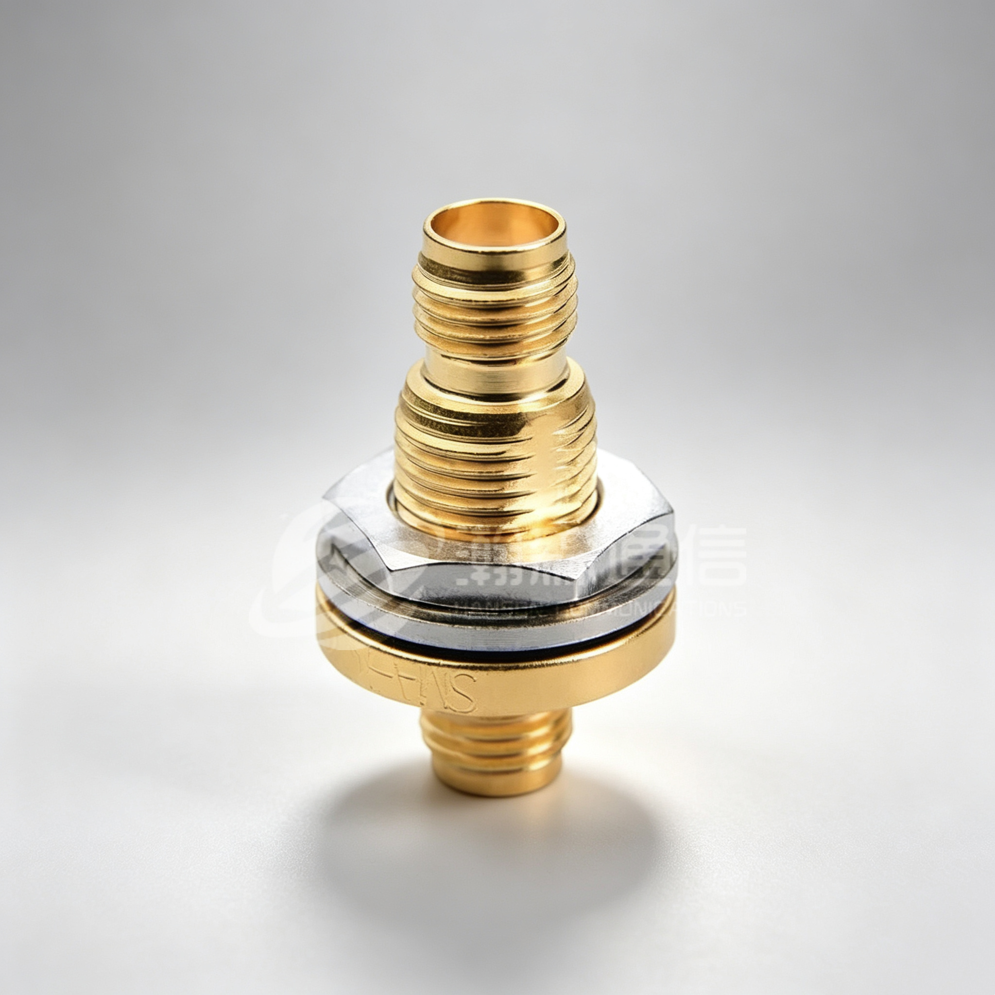
 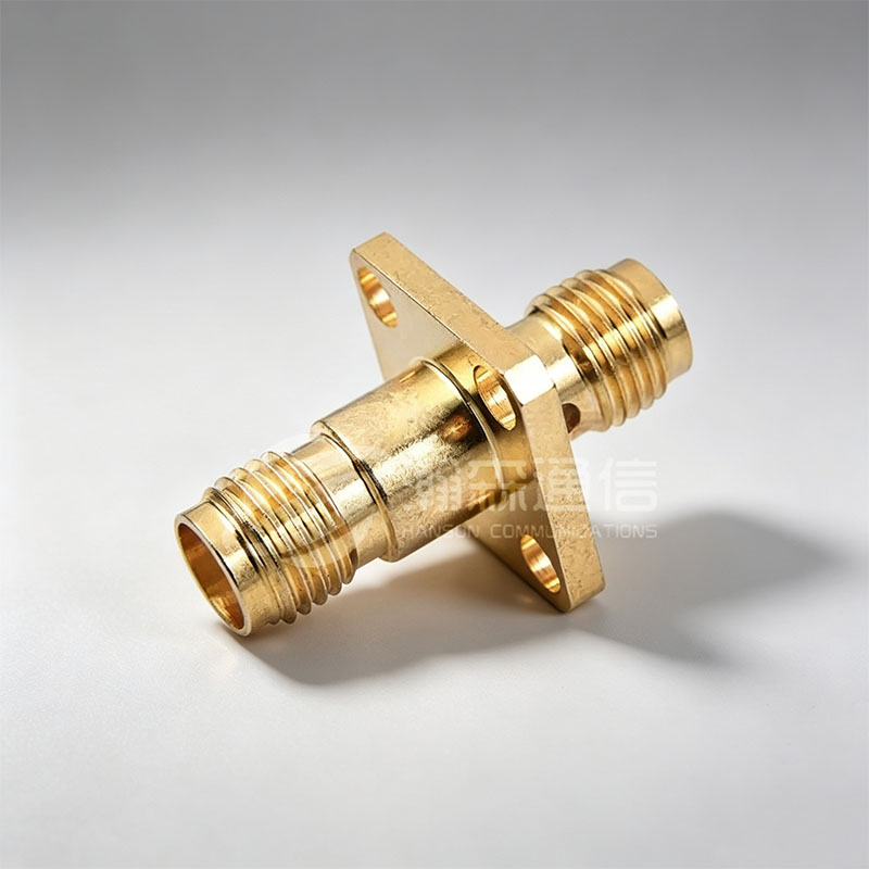 SMA to SMA RF Coaxial Adapter for Device BridgingThis adapter ensures precise, low-VSWR connections between SMA ports, ideal for linking device ports to test cables in high-frequency setups up to 18 GHz.View Product → to bridge between device ports and test cables. For long cable runs, a
 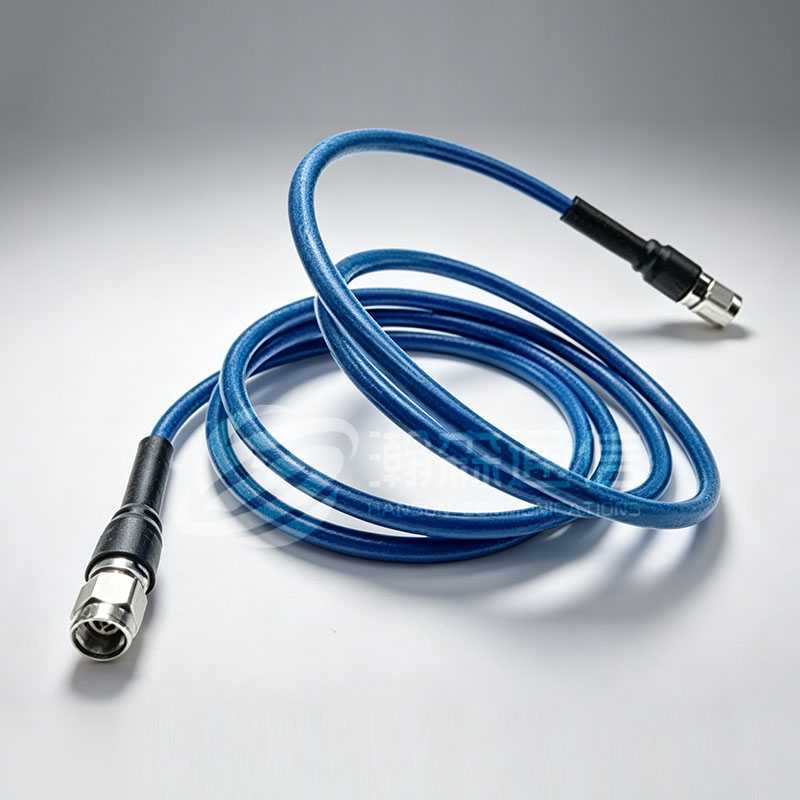 Super Low-Loss Flexible Cable Assembly for Long RunsDesigned for minimal signal loss and phase stability, this flexible assembly maintains low VSWR over long distances, suiting satellite and 5G systems.View Product → reduces insertion loss and maintains low VSWR.
Isometric Illustration: Standing Wave Pattern
The 3D sketch below shows a transmission line with an impedance mismatch at the load. The incident wave (blue) and reflected wave (red) combine to create a standing wave pattern (purple), which is what VSWR measures. The ratio of maximum to minimum amplitude is the VSWR value.
Frequently Asked Questions About VSWR and Return Loss
Q1: What is the relationship between VSWR and return loss?
They are mathematically inverse. Higher VSWR means lower return loss. The formula is: Return Loss (dB) = -20 log((VSWR-1)/(VSWR+1)).
Q2: What is a good VSWR for RF connectors?
For most systems, a VSWR below 1.5:1 (return loss >14 dB) is acceptable. High-performance systems aim for 1.2:1 (return loss >20 dB).
Q3: How do I measure VSWR or return loss?
Use a vector network analyzer (VNA) or a directional coupler with a spectrum analyzer. Many modern VNAs display both values simultaneously.
Q4: Can a bad connector cause high VSWR?
Absolutely. Damaged or poorly installed connectors are a leading cause of impedance mismatch. Always inspect and torque to spec.
Q5: What is the difference between return loss and insertion loss?
Return loss measures reflected power due to mismatch. Insertion loss is the total power lost as the signal travels through a component (includes both mismatch and dissipative losses).
Q6: How do I convert 1.25 VSWR to return loss?
Γ = (1.25-1)/(1.25+1)=0.111. Return Loss = -20 log(0.111) ≈ 19.1 dB. This is a very good match.

Looking For Business Opportunity?
Request for a call today
-

+86-15715730755
-

-

No. 1, Longcao Road, Dongqian Lake Tourism Resort Industrial Zone, Yinzhou District, Ningbo City, Zhejiang, China.
Message
Copyright © Ningbo Hanson Communication Technology Co., Ltd.
