


 English
 русский
Industry News
 Home / News / Industry News / Coaxial Connector Types Chart: RF Series, Frequency and Impedance Guide
 Coaxial Connector Types Chart: RF Series, Frequency and Impedance Guide
 2026.09.30
 Industry News
A jumper comes off the bench, is offered up to a spectrum analyser port, and will not seat. Nothing is broken. One end is an SMA, the other a 2.4 mm; both are 50 Ω, both look like the same threaded barrel, and they are not intermateable. A coaxial connector types chart exists to stop that order before it is placed, by putting impedance, frequency ceiling, coupling mechanism and interface standard on a single page.
The conclusion first: four columns decide whether a connector will work in a link. Impedance (50 Ω or 75 Ω), maximum operating frequency, coupling style, and the mechanical interface standard. Everything else, from plating to cable attachment, refines those four. The rest of this guide shows how to read such a chart, where each family actually sits, and which mistakes a chart will not catch on its own.
Content
- 1 What a Coaxial Connector Types Chart Has to Show
- 2 Coaxial Connector Types at a Glance
- 3 Frequency Ceilings, Plotted
- 4 50 Ω or 75 Ω: The Column People Skip
- 5 Coupling Mechanism and Physical Size
- 6 The Precision Series: 3.5 mm, 2.92 mm, 2.4 mm, 1.85 mm and 1.0 mm
- 7 Hermetically Sealed Variants on the Same Chart
- 8 From Connector to Cable Assembly
- 9 A Procurement Checklist Before the Order Goes Out
- 10 Turning the Chart into an Order
- 11 FAQ: Coaxial Connector Types
- 11.1 Q1. What are the most common coaxial connector types?
- 11.2 Q2. What is the difference between 50 ohm and 75 ohm coaxial connectors?
- 11.3 Q3. Can SMA and 2.92 mm connectors be mated?
- 11.4 Q4. Which coaxial connector type is best above 40 GHz?
- 11.5 Q5. What is a hermetically sealed coaxial connector used for?
- 11.6 Q6. How do I use a coaxial connector types chart to choose a part?
What a Coaxial Connector Types Chart Has to Show
A useful chart is not a list of part numbers, it is a compatibility map. Once you know what an RF coaxial connector is and how the signal runs from centre contact to outer shield, the chart becomes a filter: start with the frequency you need, discard everything whose ceiling is lower, then narrow by impedance, then by panel space.
- Impedance: 50 Ω for communications, test and radar; 75 Ω for video, broadcast and CATV. The two are not interchangeable, and the difference is often invisible on the part itself.
- Frequency ceiling: the highest frequency at which the interface still holds a defined VSWR. Above it, the connector stops behaving like a transmission line and starts behaving like an antenna.
- Coupling: threaded, bayonet, snap-on or blind-mate. This sets mating speed, vibration resistance and how tightly connectors can be packed on a panel.
- Interface standard: the mechanical gauge that guarantees two connectors of the same series mate and hold tolerance. MIL-STD-348 and IEC 61169 are the usual references, and the thread callout, such as 1/4-36 UNS-2A on SMA, is part of it.
Coaxial Connector Types at a Glance
Most catalogue charts cover fifteen to twenty-five series. The table below compresses the ones that appear in the large majority of RF projects, with the numbers that actually decide compatibility.
| Series | Impedance | Typical max frequency | Coupling | Typical use |
|---|---|---|---|---|
| BNC | 50 / 75 Ω | 4 GHz | Bayonet | Test leads, video, instrumentation |
| TNC | 50 Ω | 11 GHz | Threaded | Mobile radio, antenna feeders |
| N | 50 / 75 Ω | 11 GHz | Threaded | Base stations, outdoor antennas |
| SMA | 50 Ω | 26.5 GHz | Threaded, 1/4-36 | Instrumentation, GPS, Wi-Fi |
| TNC / SMB | 50 / 75 Ω | 4 to 11 GHz | Threaded, snap-on | Dense panels, blind mating |
| MCX / MMCX | 50 Ω | 6 GHz | Snap-on | Portable devices, modules |
| 7/16 DIN | 50 Ω | 7.5 GHz | Threaded | High power, low PIM sites |
| 4.3-10 | 50 Ω | 6 GHz | Threaded | Compact low PIM base station |
| SMP / SMPM | 50 Ω | 40 / 65 GHz | Blind-mate push-fit | Radar, satellite, high density boards |
| 3.5 mm / 2.92 mm | 50 Ω | 34 / 40 GHz | Threaded, SMA compatible | Calibration, test ports |
| 2.4 mm | 50 Ω | 50 GHz | Threaded | High-speed test, millimetre wave |
| 1.85 mm / 1.0 mm | 50 Ω | 67 / 110 GHz | Threaded | Millimetre-wave laboratory work |
Read the table as a filter rather than a ranking. A BNC is not a worse connector than an SMA; it is a bayonet-coupled 4 GHz interface that mates in a quarter turn and costs less, which is exactly what a bench test lead needs. An N-type is not obsolete next to a 2.4 mm either, because it handles far more average power and survives weather on a mast.
Where a series is offered in both 50 Ω and 75 Ω versions, the two are usually similar in appearance but not compatible in a 50 Ω system, and the difference is sometimes marked by nothing more than a colour band or a single character in the part number.
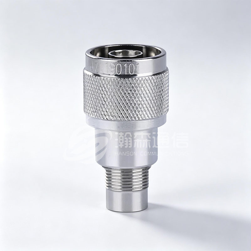
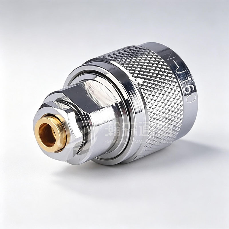 N-type RF Coaxial ConnectorThe N-type series RF coaxial connector is a RF coaxial connector with a threaded connection mechanism developed and produced in accordance with the US military standar...View Product →
Frequency Ceilings, Plotted
The single most useful column in any chart is the top frequency. Plotted on one axis, the families separate into two clear groups.
Chart 1. Nominal upper frequency limit by connector series, based on commonly published interface specifications.
The distance between SMA at 26.5 GHz and 2.4 mm at 50 GHz is not marketing. It comes from geometry: as frequency rises, the wavelength inside the interface approaches the dimensions of the outer conductor, and any slot, step or eccentricity begins to radiate energy out of the line. Precision interfaces shrink the dielectric bead and tighten the tolerance band on the centre contact and outer conductor, pushing the first higher-order mode upward.
Two practical consequences follow. Buying a precision connector for a 6 GHz link buys nothing except cost and fragility. Pushing a standard SMA past its rating often looks acceptable on a short bench test, then fails once temperature cycling moves the bead.
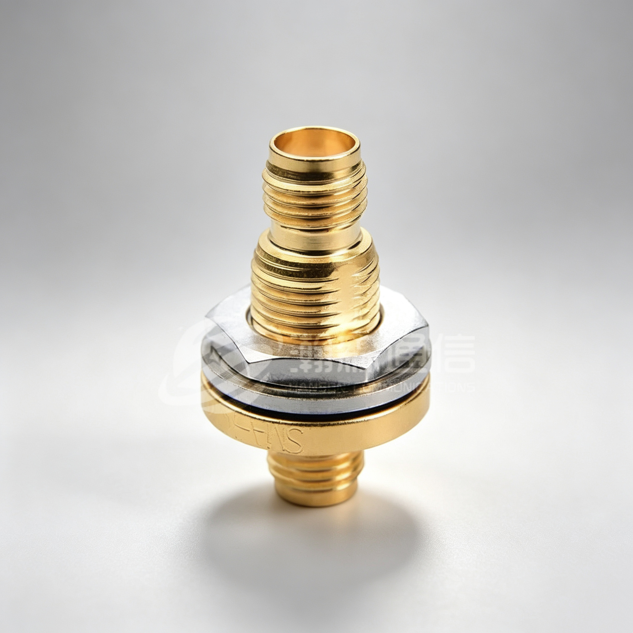
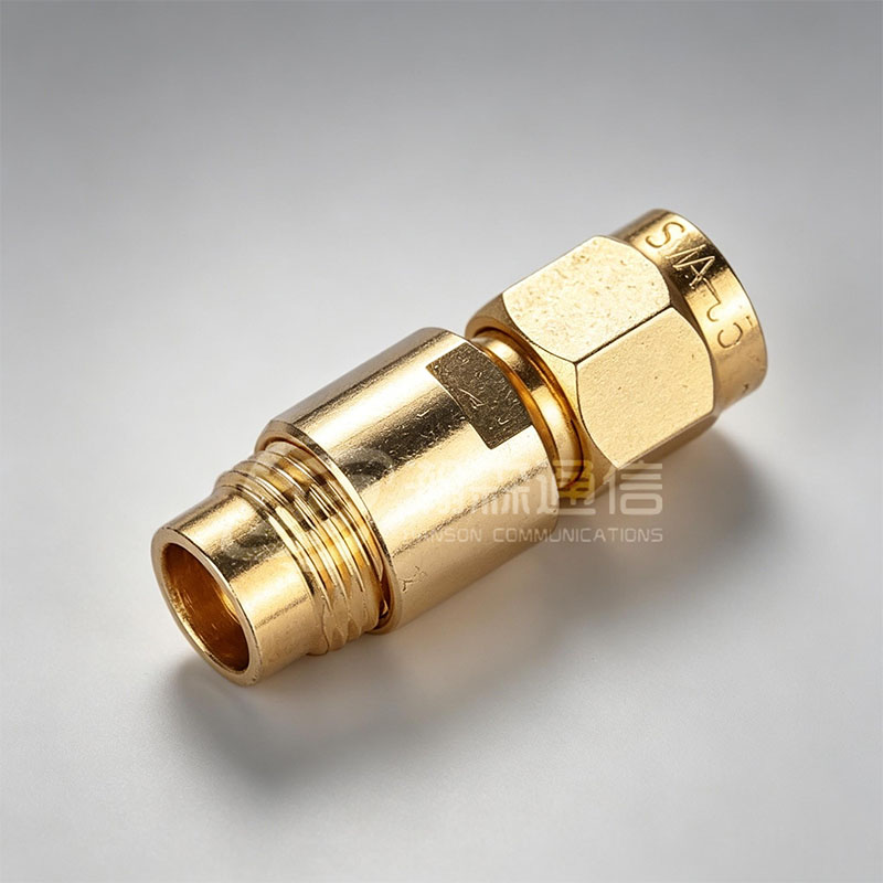 SMA ConnectorSMA RF coaxial connector is a RF coaxial connector with a threaded connection mechanism developed and produced according to the US military standard MIL-C-39012. It ha...View Product →
50 Ω or 75 Ω: The Column People Skip
Video and broadcast infrastructure runs on 75 Ω. Communications, test, radar and most instrumentation run on 50 Ω. The families share names such as BNC and N, but not geometry, and forcing one into the other produces a reflection that no torque value will cure.
How to tell them apart
On BNC and N parts the difference is often a colour code or a suffix in the part number rather than a visible dimensional change, so the impedance column is worth checking even when two parts look identical in a photograph.
What a mismatch actually costs
A deliberate 50/75 transition can be handled with a matching pad or a proper adapter. An accidental one appears as ripple across the band, and it is routinely misdiagnosed as a cable or amplifier fault because the connector itself looks correct.
Coupling Mechanism and Physical Size
Coupling style decides how fast a system can be assembled and how well it survives vibration. Bayonet BNC mates in a quarter turn. Threaded interfaces such as SMA, N, TNC and 7/16 DIN hold torque under vibration but take longer to assemble. Snap-on types such as SMB, MCX and MMCX suit dense panels where fingers cannot reach. Blind-mate types such as SMP and SMPM are designed for board-to-board stacking with a defined float.
Chart 2. Approximate coupling-nut across-flats dimension for common threaded and bayonet series.
Size tracks frequency in the opposite direction. A larger interface carries more average power and tolerates looser machining, but its upper frequency limit falls. The 19 mm coupling nut of an N-type is what lets it handle high power at a base station; the same nut makes it unusable at 30 GHz.
The Precision Series: 3.5 mm, 2.92 mm, 2.4 mm, 1.85 mm and 1.0 mm
This is where charts cause the most expensive errors. SMA, 3.5 mm and 2.92 mm share a 1/4-36 thread and will physically mate, although pairing a precision air-dielectric connector with a polymer-dielectric SMA wears the precision part slightly on every connection. The 2.4 mm and 1.85 mm interfaces form a compatible pair covering 50 GHz and 67 GHz. The 1.0 mm interface reaches 110 GHz and mates with nothing larger.
The procurement rule is simple: treat the precision connector as the reference and every mating as a wear event. Reusable test connectors are rated for a limited number of cycles, and one damaged centre contact on a 2.4 mm interface can degrade an entire measurement path without any visible damage.
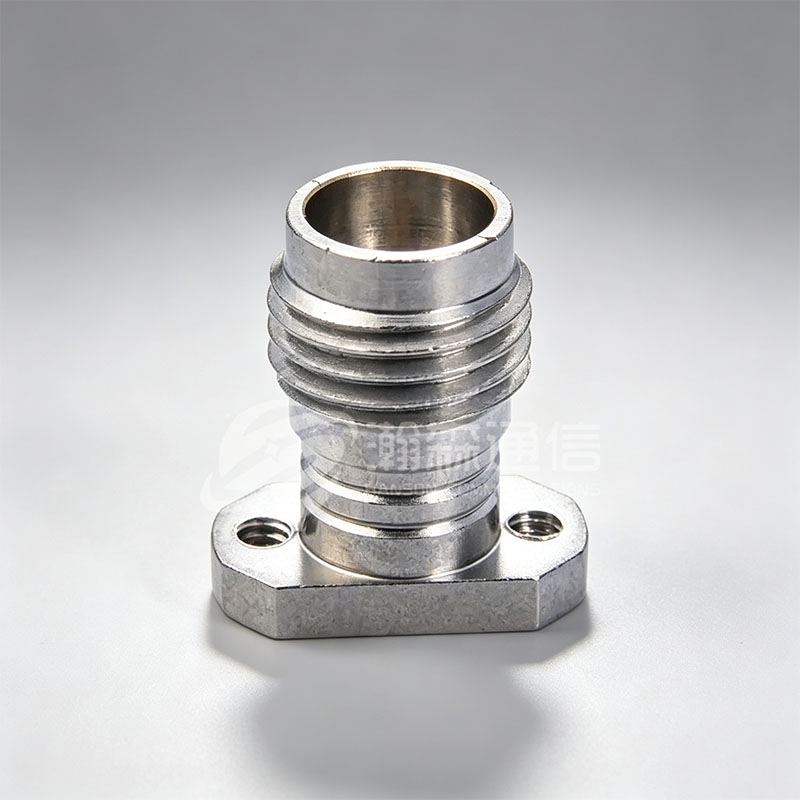
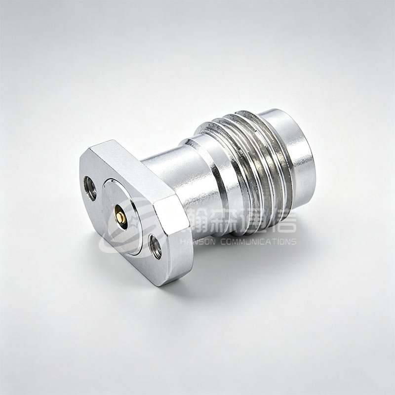 2.4mm RF Coaxial ConnectorThe 2.4mm series connector is a high-frequency RF connector designed for high-precision, high-frequency applications, especially for signal transmission occasions that...View Product →
Hermetically Sealed Variants on the Same Chart
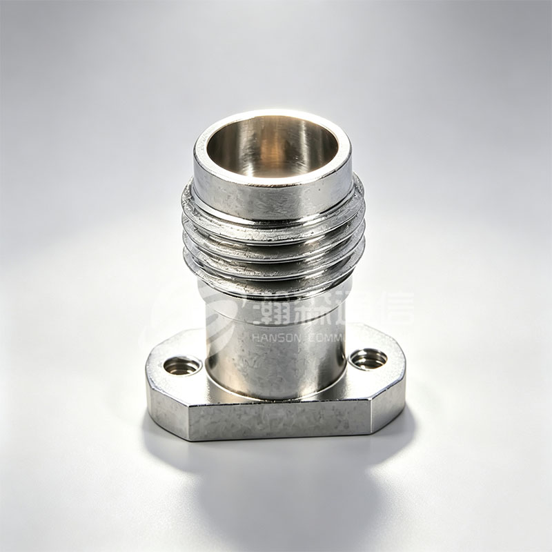
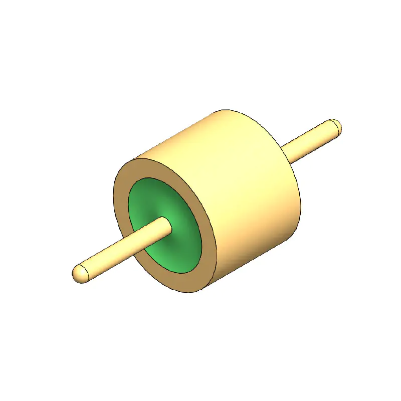
Standard connectors assume air on both sides of the panel. Where a signal must pass through a sealed enclosure, a vacuum chamber, a pressurised radar unit or a nitrogen-purged module, the connector becomes part of the seal. Hermetically sealed versions hold the centre contact with a glass-to-metal or ceramic-to-metal bond and are specified by helium leak rate rather than by dimensional tolerance alone.
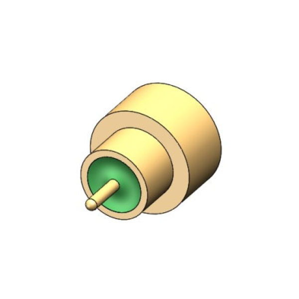
On a types chart these appear as a separate branch rather than an option on the standard series. SMP and SMPM push-fit interfaces also exist in sealed versions, which is why dense radar and satellite modules often specify them. The sealed branch adds a check no chart can perform: the glass bead diameter must match the panel cut-out, and the sealing process constrains plating options and the achievable frequency ceiling.
From Connector to Cable Assembly
A connector is one part of a cable assembly. The chart gives you the interface; the cable sets the loss, and the attachment method sets the reliability.
Figure 1. Isometric cutaway of a typical threaded coaxial cable assembly, from jacket to mating interface.
Three joint types dominate production. Solder is used for centre contacts and, on semi-rigid cable, for the braid. Crimp suits flexible cables in volume. Clamp suits large-diameter cables where a compression nut captures the braid. Each fails differently: a cold solder joint appears as intermittent loss under temperature change, while an undersized crimp shows up as rising insertion loss after vibration.
A Procurement Checklist Before the Order Goes Out
These checks catch the errors a chart cannot.
- Confirm impedance on both sides of every joint, including adapters and test leads.
- Check the frequency ceiling of the finished assembly rather than the connector alone, because the weakest element sets the limit.
- Verify the interface standard, the mating cycle rating, and whether the part is reusable or permanently installed.
- Confirm panel cut-out dimensions, sealing requirement and plating compatibility with the mating half.
- Ask for a return loss or VSWR sweep above 6 GHz on the finished assembly, not only a DC continuity test.
Turning the Chart into an Order
The chart narrows the field; a datasheet and a swept measurement close the decision. What a chart cannot tell you is who will hold the tolerance on the panel cut-out, the bead diameter and the plating at the ten-thousandth part. That question is best answered by an RF coaxial connector manufacturer with in-house machining, plating and assembly, before the first order rather than after the first failure.
FAQ: Coaxial Connector Types
Q1. What are the most common coaxial connector types?
The workhorses are SMA, BNC, TNC, N and 7/16 DIN, with SMP and SMPM for blind-mate boards and the precision series covering millimetre-wave work.
Q2. What is the difference between 50 ohm and 75 ohm coaxial connectors?
They use different centre contact and dielectric dimensions to match the system impedance. A 75 ohm plug on a 50 ohm jack creates a reflection that appears as ripple across the band.
Q3. Can SMA and 2.92 mm connectors be mated?
Yes, 2.92 mm and 3.5 mm interfaces are mechanically compatible with SMA and will mate. Because they are air-dielectric and precision made, pair them with a sacrificial adapter rather than repeated direct connections.
Q4. Which coaxial connector type is best above 40 GHz?
2.4 mm covers 50 GHz, 1.85 mm reaches 67 GHz and 1.0 mm reaches 110 GHz. Choose the smallest series that meets the target, since smaller interfaces are harder to terminate and more sensitive to contamination.
Q5. What is a hermetically sealed coaxial connector used for?
It carries RF through a sealed panel while holding a defined leak rate, using a glass-to-metal or ceramic-to-metal bond. Typical uses are vacuum chambers, pressurised radar units and outdoor modules.
Q6. How do I use a coaxial connector types chart to choose a part?
Start with the frequency, remove every series whose ceiling is lower, then filter by impedance, coupling style and panel cut-out. Confirm the final choice against the datasheet.
Looking For Business Opportunity?
Request for a call today
-

+86-15715730755
-

-

No. 1, Longcao Road, Dongqian Lake Tourism Resort Industrial Zone, Yinzhou District, Ningbo City, Zhejiang, China.
Message
Copyright © Ningbo Hanson Communication Technology Co., Ltd.
