


 English
 русский
Industry News
 Home / News / Industry News / RF Connector Types Explained: SMA, N-Type, BNC, TNC, 1.0mm to 2.4mm Guide
 RF Connector Types Explained: SMA, N-Type, BNC, TNC, 1.0mm to 2.4mm Guide
 2026.10.07
 Industry News
If you are building a 5G small cell, a bench-test rack, or a satellite ground terminal, the connector at the end of the coaxial cable is usually the last item specified and the first one to cause trouble. A 2.4 mm plug will not mate with a 1.0 mm port, a 75 ohm BNC will not preserve a 50 ohm path, and an interface rated to 4 GHz will turn a 6 GHz link into a reflection problem rather than a connection.
The short answer: most RF work today uses one of five interface families. SMA and its subminiature relatives (SMB, SMP, SMPM), N-type, TNC, BNC, and the precision planar types (3.5 mm, 2.92 mm, 2.4 mm, 1.85 mm and 1.0 mm). What separates them is frequency ceiling, impedance, coupling mechanism, mating durability, and environmental sealing. Everything below walks through those five points with the level of detail needed for a specification sheet or a purchase order.
Reader's shortcut
Frequency ceiling narrows the list first, cable diameter and connector series must match, and the environment decides whether a sealed or hermetic interface is required. Get those three right and the remaining choices are mostly about torque, mating cycles and price.
Content
- 1 The Frequency Ceiling Comes First
- 2 SMA and the Subminiature Family
- 3 N-Type, TNC and BNC: Larger Threaded and Bayonet Types
- 4 Precision Types for Millimetre-Wave Work
- 5 Hermetically Sealed and Other Specialist Types
- 6 RF Connector Types Compared Side by Side
- 7 What Actually Decides the Choice on a Project
- 8 Frequently Asked Questions About RF Connector Types
The Frequency Ceiling Comes First
Every interface family has a defined upper frequency where its geometry stops behaving like a clean 50 ohm line. Above that point, higher-order modes start to propagate inside the connector body and VSWR climbs quickly, even when the cable itself is still perfectly good. The mating geometry of the common families is standardized, which is why a 3.5 mm plug from one supplier mates with a 3.5 mm jack from another; interface dimensions for SMA, N-type, BNC and TNC are defined in MIL-STD-348 and the IEC 61169 series.
The ceilings engineers most often quote are: BNC about 4 GHz, TNC and N-type about 11 GHz, SMA 26.5 GHz, 2.92 mm 40 GHz, 2.4 mm 50 GHz, 1.85 mm 67 GHz, and 1.0 mm 110 GHz.
Values follow the limit frequencies commonly published for these interfaces in connector datasheets and RF interface standards.
Put the working frequency of the design against this list and choose the first interface that clears it with margin. A 26.5 GHz SMA carrying a 24 GHz signal has almost nothing left for the impedance bump of a cold solder joint or a worn test cable.
SMA and the Subminiature Family
SMA is the default 50 ohm threaded interface for instrumentation, antennas and radios up to 26.5 GHz. It uses a 1/4-36 threaded coupling, a PTFE dielectric and a centre pin of roughly 0.9 mm. Its weaknesses are mechanical rather than electrical: the coupling nut is small, the recommended torque is around 0.8 to 1.1 N-m (7 to 10 in-lb), and a wrench used with too much enthusiasm will deform the hex and shift the reference plane. That single habit accounts for a large share of "this connector suddenly has high return loss" reports.
SMB is the snap-on version at the same scale, rated to about 4 GHz and used where quick mating matters more than bandwidth. SMP and SMPM are board-to-board blind-mate interfaces used in dense RF modules and phased arrays. SMP operates to roughly 40 GHz and SMPM to roughly 65 GHz, with a spring-loaded male side absorbing the axial tolerance that a blind mate cannot control. Where SMA is not enough but a full precision connector is hard to justify, 3.5 mm and 2.92 mm versions mate with SMA and extend the ceiling to about 33 GHz and 40 GHz.
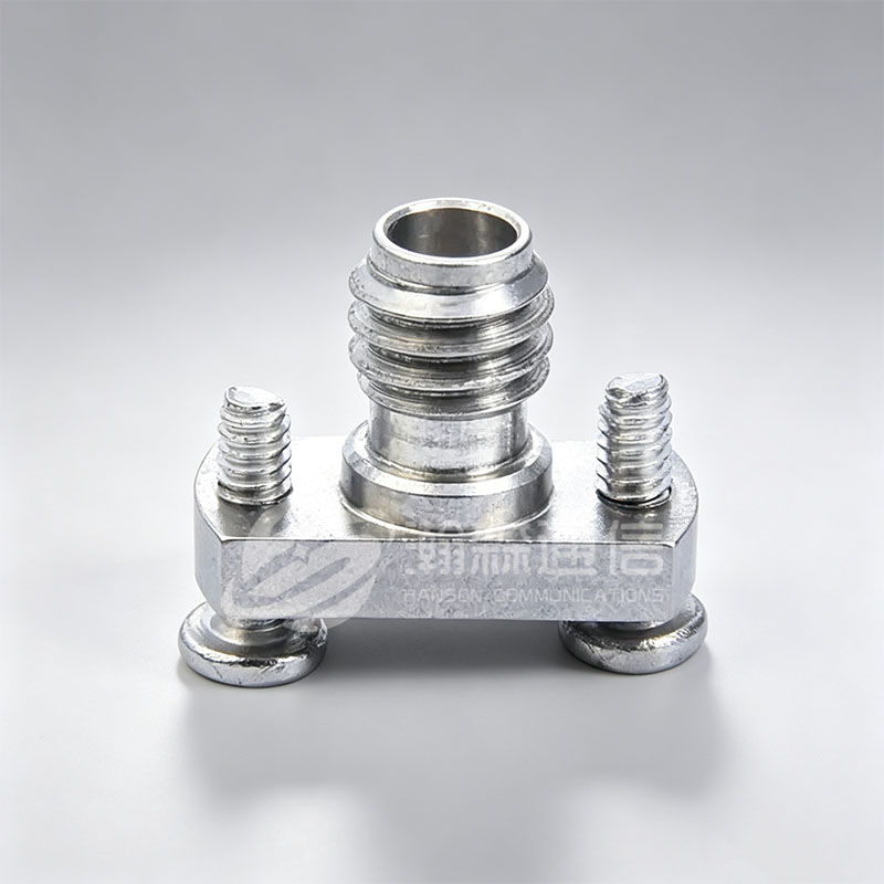
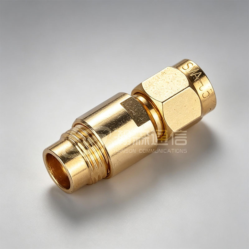 SMA ConnectorSMA RF coaxial connector is a RF coaxial connector with a threaded connection mechanism developed and produced according to the US military standard MIL-C-39012. It ha...View Product →
N-Type, TNC and BNC: Larger Threaded and Bayonet Types
N-type connectors use a 5/8-24 thread and a much larger dielectric, which is why they handle far more power than SMA and stay stable outdoors. The standard ceiling is 11 GHz, with precision versions reaching 18 GHz. Properly mated and weatherproofed, an N-type pair is the normal choice for base station antenna feeders, jumper cables and outdoor radio units, and it tolerates the cable movement that would destroy a subminiature interface.
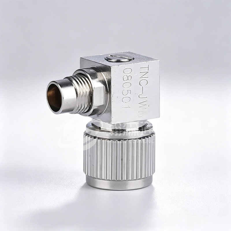
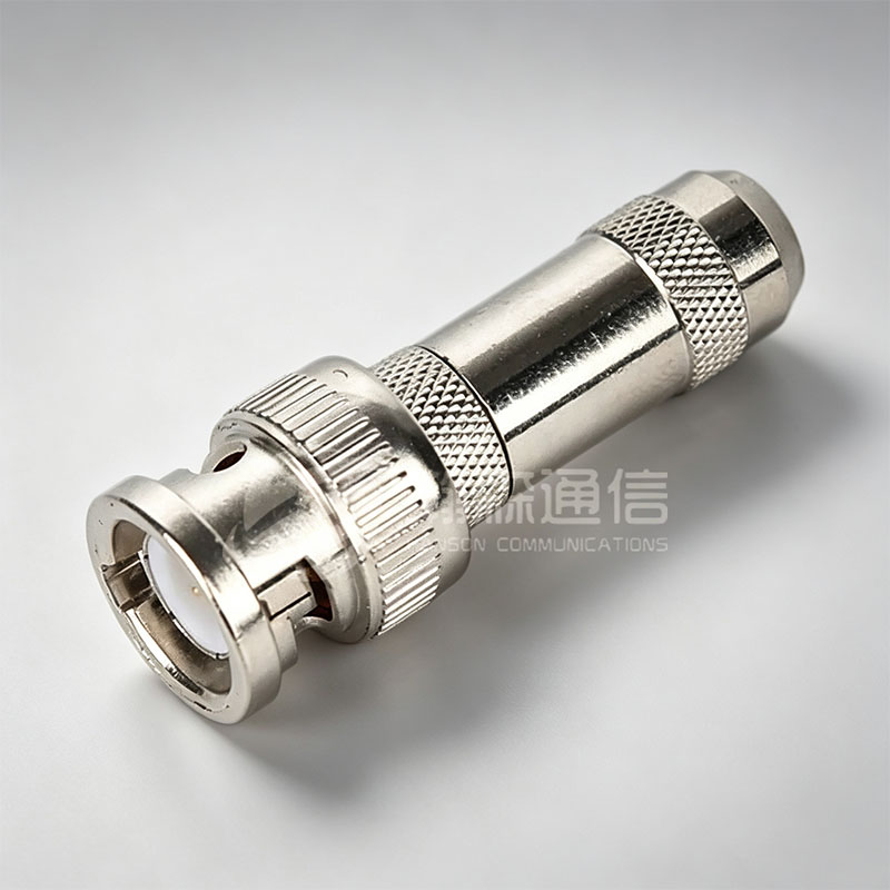
TNC is essentially a threaded BNC: the same body size, but screw coupling that holds under vibration, which is why it appears on mobile radio equipment and handheld test gear rated to about 11 GHz. BNC keeps its quarter-turn bayonet for fast patching and stops at about 4 GHz in 50 ohm form. The 75 ohm BNC used for video looks almost identical; mixing the two impedances into one RF path creates a mismatch that no amount of cable quality will fix.
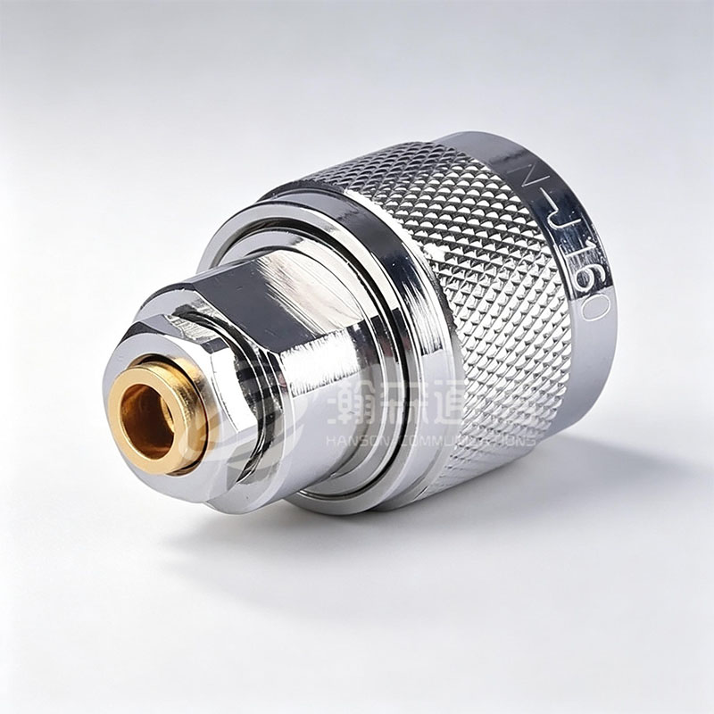 N-type RF Coaxial ConnectorThe N-type series RF coaxial connector is a RF coaxial connector with a threaded connection mechanism developed and produced in accordance with the US military standar...View Product →
Precision Types for Millimetre-Wave Work
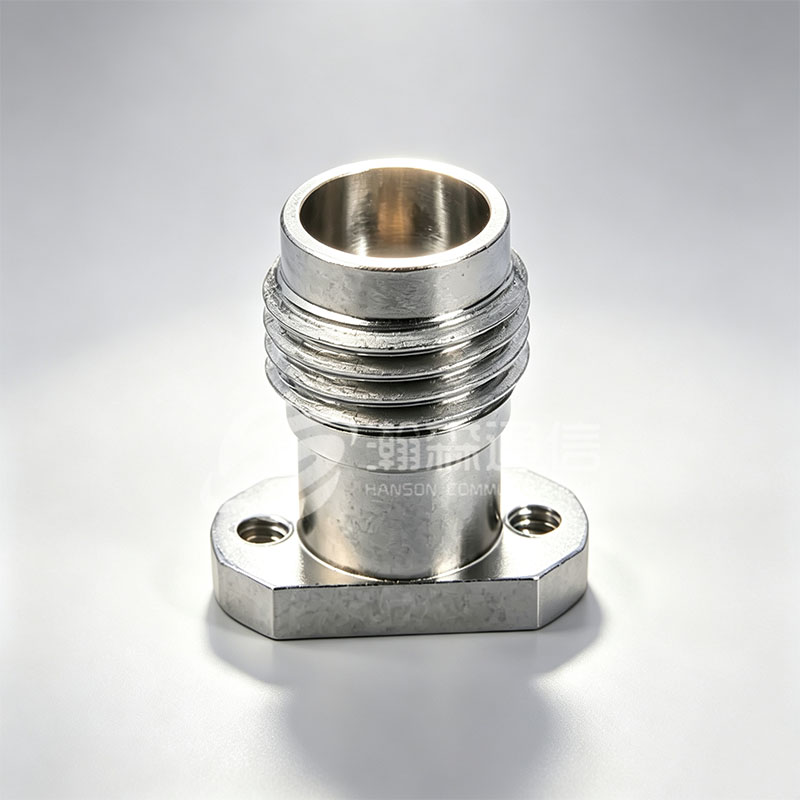
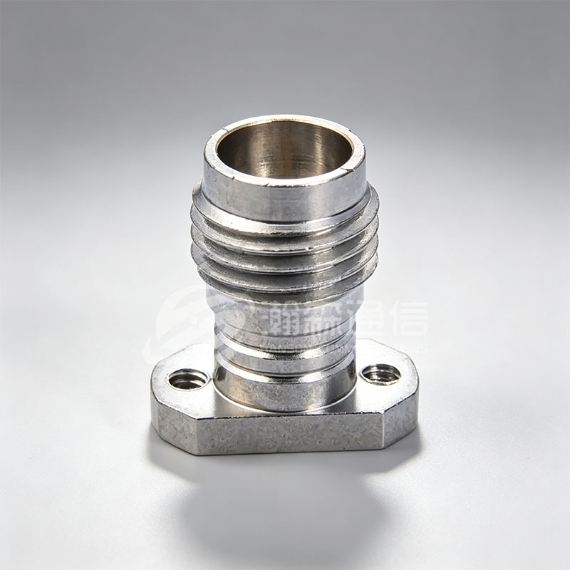
Above about 26.5 GHz the interface has to be air-dielectric and machined to tight tolerances. The 1.0 mm, 1.85 mm, 2.4 mm and 2.92 mm families share the same idea: no polymer around the centre conductor, tightly controlled bead geometry, and a reference plane defined at the mating face rather than somewhere inside the coupling nut.
2.4 mmto 50 GHz
1.85 mmto 67 GHz
1.0 mmto 110 GHz
Compatibility is where money quietly gets lost. SMA, 3.5 mm and 2.92 mm are intermateable. 2.4 mm and 1.85 mm mate with each other. 1.0 mm mates only with 1.0 mm. Forcing a worn, out-of-tolerance SMA onto a 2.92 mm or 2.4 mm test port can score that precision interface permanently, and a damaged test port quietly invalidates every measurement taken through it afterwards.
Hermetically Sealed and Other Specialist Types
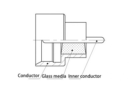
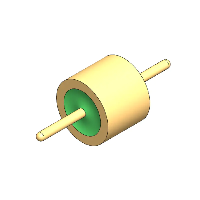
Some RF paths are not allowed to leak. Hermetically sealed connectors replace the polymer bead with a glass-to-metal seal, so the dielectric is fused to the metal shell and the centre pin rather than pressed into it. Typical helium leak-rate specifications for such parts sit in the 10-9 atm-cc/s range, and the mechanical strength comes from the seal itself rather than from an elastomer that will age.
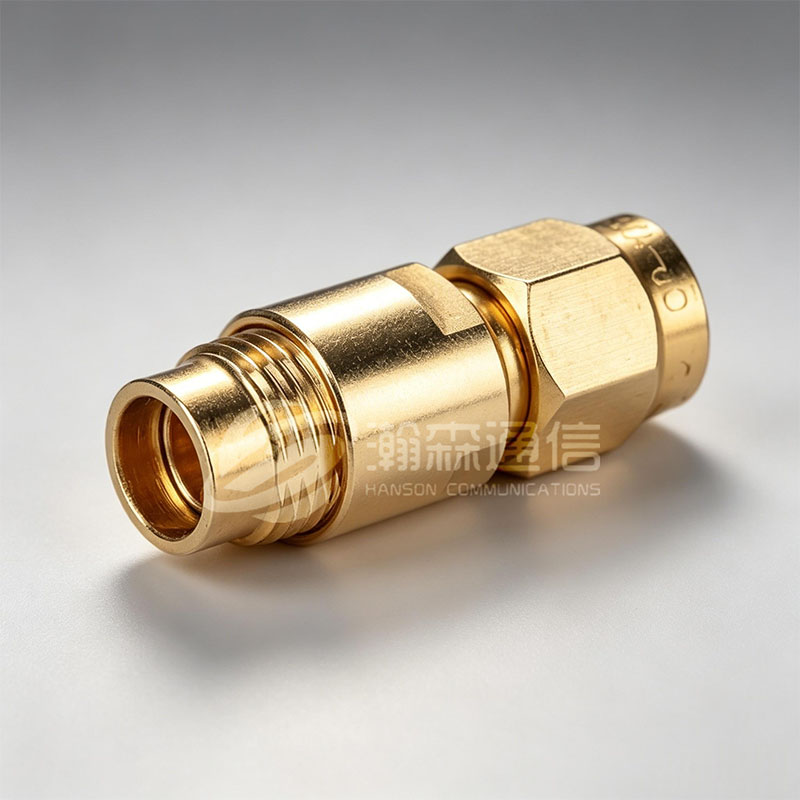
These parts appear in vacuum chambers, pressure transmitters, cryogenic systems, aerospace payloads and any enclosure where condensation would change the dielectric constant and therefore the impedance of the line. The SMP and SMPM hermetic variants are common in dense microwave assemblies where a single sealed bulkhead has to pass several coaxial lines at once.
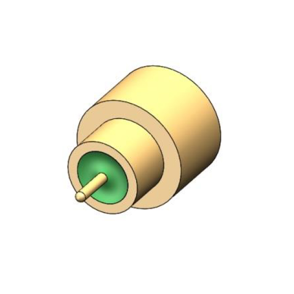
Schematic cutaway reference for a glass-sealed coaxial feedthrough; proportions are illustrative.
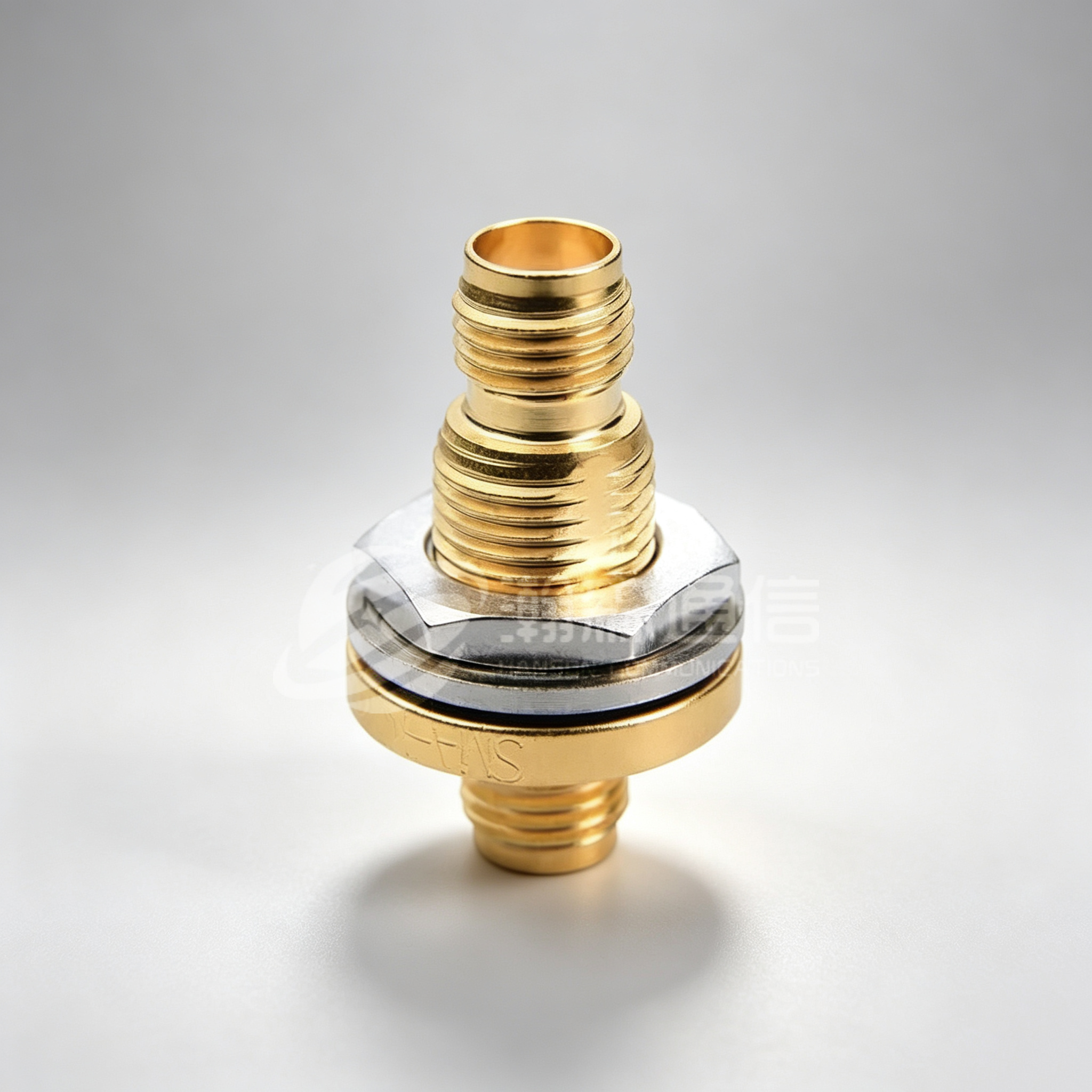
 SMPM Hermetically Sealed ConnectorSMPM (SubMiniature Push-on Micro) sealed connector is a miniaturized RF connector with full escapement, semi-escapement, and light hole, designed for high frequency, c...View Product →
RF Connector Types Compared Side by Side
| Interface | Coupling | Typical max frequency | Where it is used |
|---|---|---|---|
| SMA | 1/4-36 thread | 26.5 GHz | Test equipment, antennas, radio front ends |
| SMB | Snap-on | 4 GHz | Dense racks, quick-mate instrument ports |
| SMP / SMPM | Blind mate | 40 GHz / 65 GHz | Board-to-board modules, phased arrays |
| N-type | 5/8-24 thread | 11 GHz (18 GHz precision) | Outdoor feeders, high-power radio |
| TNC | 7/16-28 thread | 11 GHz | Mobile radio, vibration-prone equipment |
| BNC | Bayonet | 4 GHz | Lab patching, video and instrumentation |
| 2.92 mm | 1/4-36 thread | 40 GHz | Precision test ports, mmWave benches |
| 2.4 mm | M8 thread | 50 GHz | High-end VNA ports, radar modules |
| 1.85 mm | M7 thread | 67 GHz | Automotive radar, 60 GHz links |
| 1.0 mm | M5.5 thread | 110 GHz | Sub-THz research, waveguide transitions |
What Actually Decides the Choice on a Project
Frequency narrows the list to two or three candidates. Five practical constraints usually pick the final part.
- Cable compatibility. Connector series follow cable diameter, not preference. RG-316 and similar flexible cables suit SMA; RG-58 and RG-213 suit BNC, TNC and N-type; low-loss corrugated cable almost always terminates in N-type or 7/16.
- Impedance consistency along the whole chain. One 75 ohm part in a 50 ohm path produces a mismatch that shows up as return loss at exactly the frequency you care about.
- Mating cycles and torque. Standard SMA and N-type interfaces are generally quoted around 500 mating cycles; precision millimetre-wave interfaces wear faster and cost far more to replace.
- Environment. Outdoor units need an interface that seals when mated, plus the correct boot or tape wrapping. Vacuum and pressure boundaries need a glass-to-metal seal.
- Test-port protection. Keep a sacrificial adapter on bench instruments and inspect precision interfaces under magnification before every mate.
SMA N-type
Qualitative engineering comparison based on standard interface characteristics, not measured laboratory data.
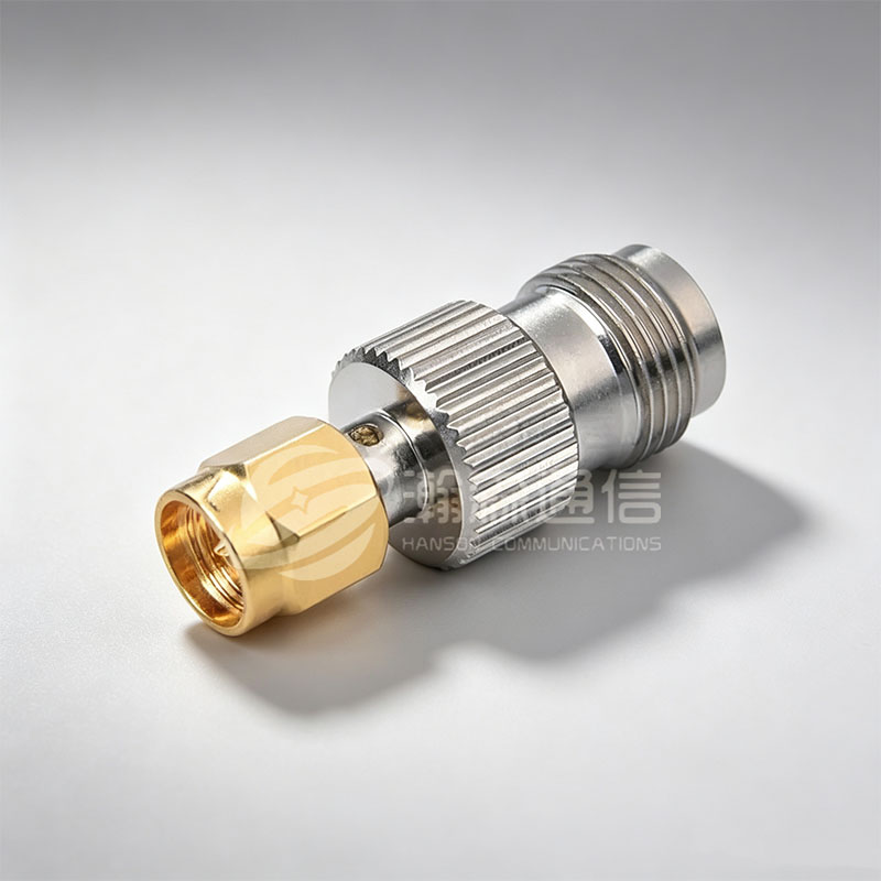
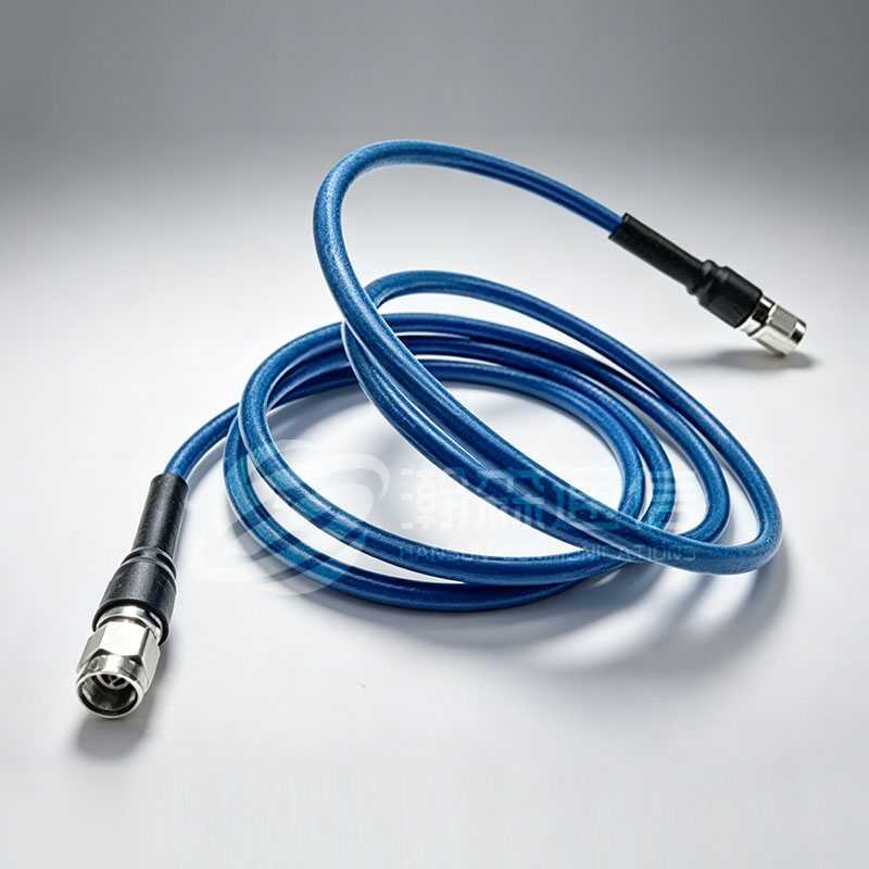
Attenuation, return loss and mechanical wear are linked more tightly than most specifications suggest; the practical causes of loss in a coaxial path are covered in this note on RF connector signal attenuation. For projects that need a specific interface, plating or cable termination, working with a manufacturer that machines its own parts usually shortens the loop between drawing and first article. Hanson Communication, an RF coaxial connector manufacturer based in Ningbo, produces SMA, N-type, TNC, BNC, precision and hermetically sealed interfaces as well as adapters and low-loss cable assemblies.
Frequently Asked Questions About RF Connector Types
Q1. What are the most common RF connector types?
SMA, N-type, BNC and TNC cover most general work, with 2.92 mm, 2.4 mm, 1.85 mm and 1.0 mm used for millimetre-wave paths. SMA runs to 26.5 GHz, N-type and TNC to about 11 GHz, and BNC to about 4 GHz.
Q2. What is the difference between an SMA and an N-type connector?
SMA is a 1/4-36 threaded subminiature interface rated to 26.5 GHz. N-type is a larger 5/8-24 interface rated to about 11 GHz with far higher power handling and much better performance outdoors.
Q3. Are 1.85 mm and 2.4 mm connectors compatible?
Yes, 1.85 mm and 2.4 mm share the same mating geometry and can be mated to each other. 1.0 mm is compatible only with 1.0 mm, and an SMA should never be forced onto any of them.
Q4. What is the maximum frequency of a BNC connector?
A 50 ohm BNC is normally rated to about 4 GHz. The 75 ohm BNC used for video is generally limited to roughly 1 GHz and is not interchangeable with the 50 ohm version.
Q5. Do RF connectors always have to be 50 ohm?
Most test, radio and antenna systems are 50 ohm. 75 ohm interfaces exist for video and broadcast, and mixing the two in one path creates a mismatch that appears as high VSWR and extra signal loss.
Q6. When should I specify a hermetically sealed RF connector?
When the RF path crosses a vacuum boundary, a pressure housing or an enclosure where moisture ingress would change the dielectric and the impedance, such as vacuum chambers, pressure transmitters and aerospace payloads.
Looking For Business Opportunity?
Request for a call today
-

+86-15715730755
-

-

No. 1, Longcao Road, Dongqian Lake Tourism Resort Industrial Zone, Yinzhou District, Ningbo City, Zhejiang, China.
Message
Copyright © Ningbo Hanson Communication Technology Co., Ltd.
