


 English
 русский
Industry News
 Home / News / Industry News / TNC Connector vs BNC: Threaded or Bayonet Coupling for Your RF Design Needs
 TNC Connector vs BNC: Threaded or Bayonet Coupling for Your RF Design Needs
 2026.10.14
 Industry News
A technician bolts a BNC-fed antenna to a mast, runs a vibration sweep, and watches the received level flutter by a few tenths of a dB. Nothing has failed. The bayonet collar has simply backed off a fraction of a turn. Refit the same cable run with a TNC and the flutter disappears, because the threaded coupling keeps the mating plane exactly where it was tightened.
That single bench observation answers most of the TNC versus BNC question. Electrically the two interfaces are near twins: both are 50 ohm designs with the same inner contact geometry, both appear in MIL-STD-348 interface drawings, and both accept similar cable sizes. What separates them is the locking mechanism, and nearly every practical difference — frequency ceiling, vibration behaviour, mating speed, outdoor sealing — traces back to that one part. Choose by the environment the joint will live in, not by brand tier or price.
Content
- 1 The Short Answer: TNC for Vibration, BNC for Speed
- 2 One Interface, Two Coupling Systems
- 3 TNC vs BNC Specifications at a Glance
- 4 Frequency Headroom: Where the BNC Stops
- 5 Vibration, Sealing, and Mechanical Reliability
- 6 Choosing by Application
- 7 Procurement Details That Decide the Outcome
- 8 Frequently Asked Questions
- 8.1 Q1: What is the main difference between a TNC and a BNC connector?
- 8.2 Q2: Can a TNC connector replace a BNC connector?
- 8.3 Q3: What is the frequency range of TNC and BNC connectors?
- 8.4 Q4: Are TNC connectors waterproof?
- 8.5 Q5: Which is better for CCTV and video, BNC or TNC?
- 8.6 Q6: Do BNC and TNC connectors have the same impedance?
The Short Answer: TNC for Vibration, BNC for Speed
If you have ten seconds: pick the TNC when the joint must stay tight under shock, vibration, or long unattended service; pick the BNC when the joint will be mated and unmated by hand, often, in a controlled environment. Four rules cover most decisions:
- Threaded coupling wins wherever vibration is continuous — vehicle mounts, antenna masts, machine-mounted radios.
- Bayonet coupling wins on speed and blind mating — patch panels, bench instruments, and video racks where a quarter turn beats several full turns.
- Frequency headroom favours the TNC; the bayonet slot and its mechanical play start to cost return loss well before the theoretical limit.
- Impedance and cable fit are identical, so the real question is never "which one is better" but "which one stays mated in my environment".
One trap before anything else: confirm you are comparing a 50 ohm BNC with a 50 ohm TNC. The 75 ohm BNC used in video work looks the same but is a different interface, and mixing 50 and 75 ohm parts creates reflections that no coupling design can fix.
One Interface, Two Coupling Systems
Inside the outer body, a BNC and a TNC are the same connector. Both use a 50 ohm air-dielectric interface with a defined inner contact diameter and a mating plane controlled by the outer body dimensions. The difference sits entirely on the outside.
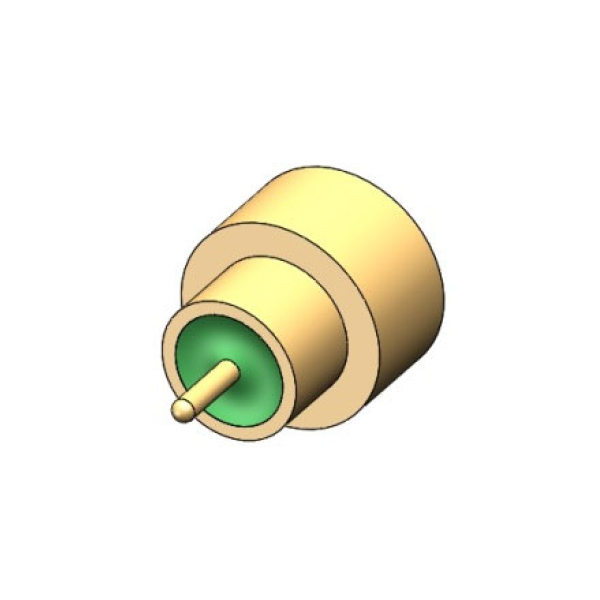
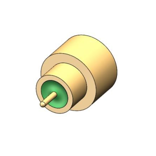
The BNC uses a bayonet: two lugs on the plug drop into slots in the jack, a quarter turn locks them, and a spring washer holds the engagement. The TNC keeps the identical inner geometry and replaces those lugs with a fine-pitch thread, so the plug is screwed down until the mating faces seat.
Isometric view of the two coupling systems. The BNC bayonet locks in a quarter turn; the TNC thread needs several full turns to seat the mating faces.
Because the inner contacts match, BNC and TNC hardware behaves almost identically below about 1 GHz, where the coupling method contributes very little to the electrical result. The further you push frequency and the harsher the mechanical environment, the more the two designs separate.
TNC vs BNC Specifications at a Glance
The table below lists the values an RF engineer actually checks when these two interfaces are shortlisted. All figures describe 50 ohm versions unless stated otherwise.
| Parameter | BNC | TNC |
|---|---|---|
| Coupling mechanism | Bayonet, roughly a quarter turn | Threaded, several full turns |
| Standard impedance | 50 ohm and 75 ohm | 50 ohm (75 ohm variants uncommon) |
| Typical upper frequency | About 4 GHz at 50 ohm; about 1 GHz for 75 ohm video | About 11 GHz |
| Vibration behaviour | Collar can back off, producing micro-disconnections | Thread maintains preload and stable contact pressure |
| Mating speed | Fast, often one-handed | Slower, needs two hands and a torque check |
| Sealing options | Limited; rarely the first choice outdoors | Gasketed and sealed variants widely available |
| Interface reference | MIL-STD-348; IEC 61169 series | MIL-STD-348; IEC 61169 series |
| Mating cycles, typical datasheet value | Around 500 | Around 500 |
| Mates with the other type | No | No |
Frequency Headroom: Where the BNC Stops
Frequency is where the coupling question becomes an electrical one. A clean bayonet joint is perfectly usable to roughly 4 GHz in 50 ohm form, and plenty of system designs stay below 1 GHz, where the difference is invisible. Push past 2 to 3 GHz, however, and the mechanical looseness of the bayonet shows up as variation in return loss rather than a fixed number.
The threaded TNC holds the mating plane at a repeatable distance, which keeps the impedance transition consistent and extends practical operation to about 11 GHz — the same order of magnitude as an N-type connector, in a body small enough for dense panel layouts.
Typical upper operating frequency for 50 ohm interfaces, based on common MIL-STD-348 derived datasheet values. SMA and N-type are shown for context only.
If your signal chain is sensitive to reflections, the interface is only half the story; the cable, the crimp or solder joint, and the mating torque matter just as much. The mechanics behind how RF coaxial connectors affect signal quality are worth reviewing alongside the interface choice.
Vibration, Sealing, and Mechanical Reliability
Vibration is where the two genuinely diverge. Under a continuous sweep, a bayonet collar can creep backwards until contact pressure drops, producing short micro-disconnections that appear as intermittent level jumps rather than a clean failure. Engineers running MIL-STD-202 style vibration profiles see this as an unstable reading, which is exactly the condition threaded coupling was designed to remove.
Sealing follows the same logic. A bayonet joint relies on spring force that a gasket will fight, so sealed BNC designs stay limited. A threaded joint can carry a gasket or O-ring and still hold preload, which is why TNC variants dominate outdoor antenna feeds, mobile radio mounts, and weather-exposed enclosures.
Qualitative comparison based on coupling design and typical datasheet conventions, not on measured test data. Ratings run from 1 (weak) to 5 (strong).
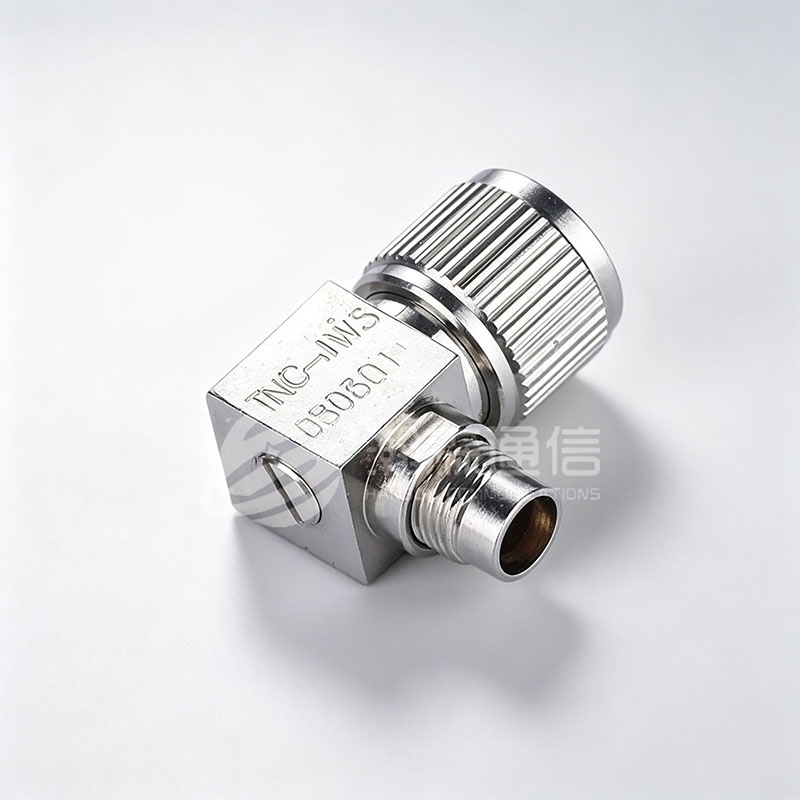 TNC Threaded RF Coaxial ConnectorsThreaded TNC connectors with predictable mating force, sealing capability, and 50Ω performance up to 18GHz for outdoor antenna feeds and radio equipment.View Product →
Mating life is one place where the two are closer than people expect: most datasheets for both interfaces specify roughly 500 mating cycles. The TNC advantage is not longer life in absolute terms but more predictable life, because every mate applies consistent axial force instead of relying on a spring's memory.
Choosing by Application
Match the coupling to the environment, and the decision usually makes itself:
- Video and broadcast work: 75 ohm BNC, because both the impedance and the fast patch-panel workflow fit the job.
- Bench and laboratory instruments: 50 ohm BNC for equipment swapped several times a day; the quarter turn saves real time across a working week.
- Outdoor antenna feeds and mobile radio: TNC, where wind, thermal cycling, and vibration keep working on the joint.
- Avionics, rail, and vehicle-mounted equipment: TNC, primarily for vibration resistance.
- Panel layouts pushing above 4 GHz: TNC, or SMA if density matters less than the frequency ceiling.
- Systems already built around SMA: keep the SMA interface and bridge with an adapter rather than re-terminating the whole harness.
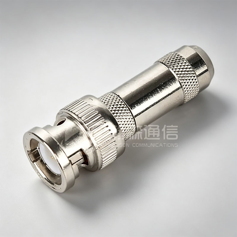 BNC Bayonet RF Coaxial ConnectorsBayonet-locking BNC connectors for rapid, reliable RF connections, available in 50Ω and 75Ω versions with up to 4GHz and 1GHz frequency ranges.View Product →
Procurement Details That Decide the Outcome
Once the interface is settled, the result depends on details that look minor on a quotation. Work through this list before releasing a purchase order:
- Impedance consistency. Confirm the whole bill of materials is 50 ohm, including adapters and bulkhead feedthroughs. A single 75 ohm part in a 50 ohm chain creates a reflection you cannot tune out.
- Cable and termination match. BNC and TNC bodies are sold for specific cable families; the wrong ferrule or crimp die produces a joint that looks correct and fails on the first thermal cycle.
- Contact plating. Gold-plated contacts are the norm for repeated mating; nickel suits a mate-once installation but not a patch panel.
- Mating torque and wrench flats. Threaded TNC coupling needs a defined torque. Ask for the recommended value and check that the geometry allows a torque wrench.
- Sealing and temperature range. For outdoor use, confirm gasket material and operating temperature range in writing, not just "weatherproof" in a description.
- Assembly practice. Most field failures are installation failures, which is why proper RF coaxial connector installation belongs on the incoming inspection checklist, not only in the manual.
When a system already uses SMA and only a short run needs the vibration-resistant interface, an adapter is often cheaper than re-terminating an entire harness.
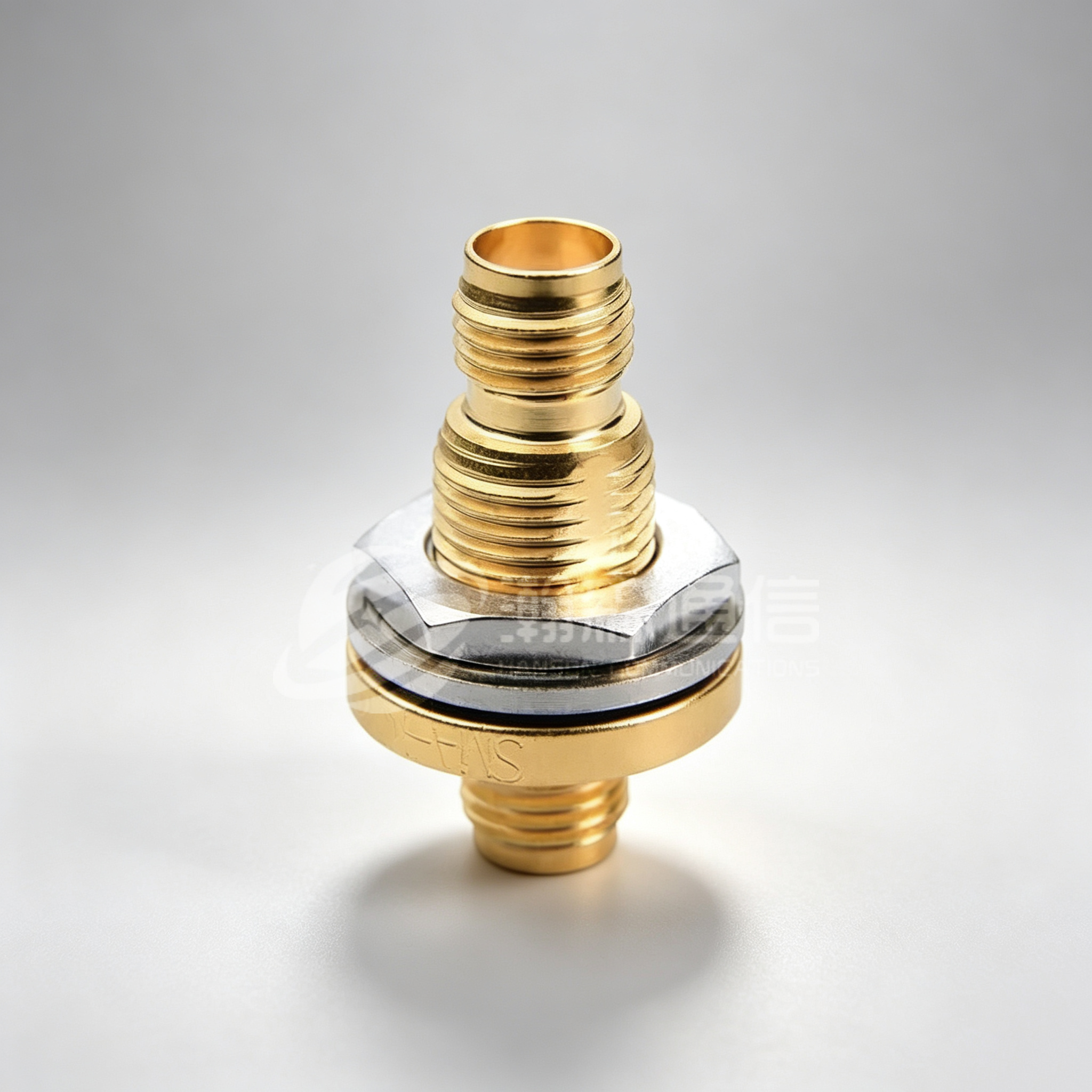
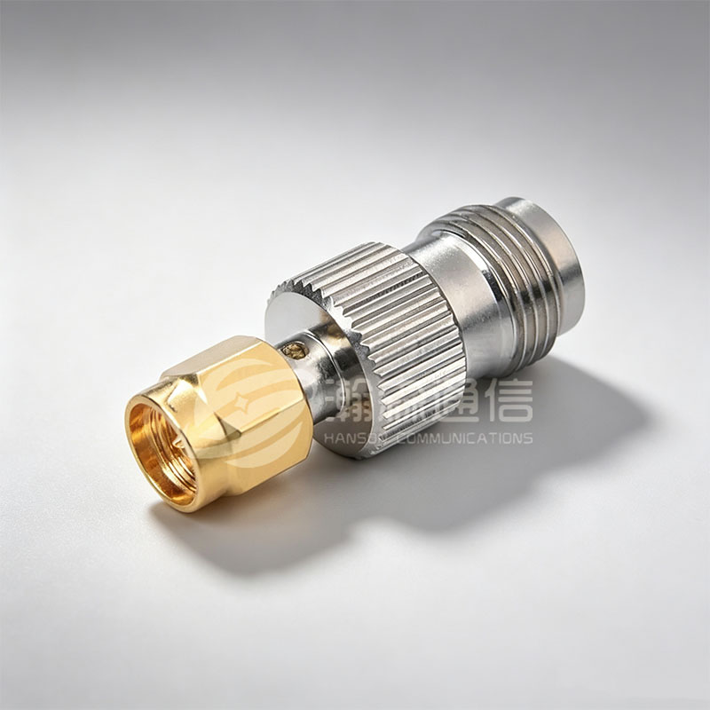 SMA to TNC RF Coaxial AdapterAdapter joining SMA to threaded TNC connectors for RF/microwave systems, offering DC-18GHz operation, VSWR 1.15, and stable signal transmission.View Product →
Frequently Asked Questions
Q1: What is the main difference between a TNC and a BNC connector?
The locking mechanism. A BNC locks with a quarter-turn bayonet; a TNC screws on with a thread. The inner 50 ohm interface is essentially the same, so the difference shows up mechanically and at higher frequencies.
Q2: Can a TNC connector replace a BNC connector?
Not directly. BNC and TNC do not mate with each other, even though their inner contacts are similar. You must change both halves of the pair, or bridge them with an adapter.
Q3: What is the frequency range of TNC and BNC connectors?
A 50 ohm BNC is typically usable to about 4 GHz, while a TNC extends to roughly 11 GHz. The 75 ohm BNC used for video is usually limited to about 1 GHz.
Q4: Are TNC connectors waterproof?
Not by default. Standard TNC connectors are not sealed. If you need an outdoor or weather-exposed solution, specify a gasketed or hermetically sealed variant and confirm the IP rating.
Q5: Which is better for CCTV and video, BNC or TNC?
BNC, almost always. Video systems are built around 75 ohm impedance and BNC patch panels, so switching to threaded coupling would add cost without improving picture quality.
Q6: Do BNC and TNC connectors have the same impedance?
Both are commonly made in 50 ohm, and the BNC is also widely available in 75 ohm. Always verify the impedance of the specific part before mixing it into an existing 50 ohm signal chain.


Looking For Business Opportunity?
Request for a call today
-

+86-15715730755
-

-

No. 1, Longcao Road, Dongqian Lake Tourism Resort Industrial Zone, Yinzhou District, Ningbo City, Zhejiang, China.
Message
Copyright © Ningbo Hanson Communication Technology Co., Ltd.
