


 English
 русский
Industry News
 Home / News / Industry News / Miniature RF Connectors: A Guide to Types, Frequency Limits, and Selection
 Miniature RF Connectors: A Guide to Types, Frequency Limits, and Selection
 2026.09.09
 Industry News
You are laying out a 28 GHz phased-array board and the space between modules is barely 5 mm. A standard N-type connector will not fit, and an improperly chosen small connector could add 0.3 dB of loss and a reflection that disturbs the antenna pattern. The conclusion is direct: miniature RF connectors are not just smaller versions of big connectors; they are precision interfaces with their own frequency limits, coupling mechanics, and reliability constraints. This guide explains what counts as a miniature RF connector, how common types compare, and which specification matters most during selection.
Content
- 1 What Counts as a Miniature RF Connector?
- 2 Miniature Connector Types Compared
- 3 How to Choose the Right Miniature RF Connector
- 4 Real-World Applications and Environment Considerations
- 5 Sourcing and Quality Risks
- 6 Frequently Asked Questions
- 6.1 What is the difference between SMA, SMP, and SMPM connectors?
- 6.2 Are miniature RF connectors always 50 ohms?
- 6.3 Why does VSWR increase when I use a miniature connector above its rated frequency?
- 6.4 Can I solder a miniature RF connector directly to a PCB?
- 6.5 Do hermetically sealed RF connectors need special handling?
- 6.6 How do I extend the life of a miniature RF connector?
What Counts as a Miniature RF Connector?
In RF engineering, "miniature" is used loosely. It usually refers to connector families with an outer conductor diameter below roughly 10 mm and designed for frequencies above 1 GHz. The group includes SMA, SMP, SMPM, 2.4 mm, 1.85 mm, and 1.0 mm interfaces. Some suppliers also call the smaller versions "microminiature" or "ultraminiature," but there is no universal boundary between these categories.
The key point is that miniature connectors were developed to serve compact modules without sacrificing controlled impedance — typically 50 ohms. SMA, for instance, was introduced in the 1960s as a semi-precision interface for coaxial cables. It became the de facto standard for test equipment and RF boards. Later generations such as 2.4 mm and 1.85 mm pushed frequency limits while maintaining a 50-ohm environment, and 1.0 mm now reaches into the millimeter-wave range above 100 GHz.
Miniature Connector Types Compared
Before you choose, compare the common miniature interfaces by frequency ceiling, coupling style, and physical size. The table below summarizes typical ratings; actual performance depends on cable type, material quality, and assembly.
| Interface | Frequency Range (GHz) | Coupling | Outer Conductor Diameter (mm) | Common Use |
|---|---|---|---|---|
| SMA | 0–18 (some to 27) | Threaded | 4.1 | Test ports, modules, antennas |
| SMP | 0–40 | Snap-on | 3.2 | Compact blind-mate boards |
| SMPM | 0–65 | Snap-on | 2.5 | High-density millimeter-wave |
| 2.4 mm | 0–50 | Threaded | 5.2 | Broadband test and instruments |
| 1.85 mm | 0–67 | Threaded | 4.3 | Millimeter-wave modules |
| 1.0 mm | 0–110 | Threaded | 2.6 | Sub-THz and 5G research |
Figure 1: Typical maximum frequency ratings for common miniature RF connector interfaces.
This comparison reveals why selecting by look or availability alone is risky. An SMA connector may be perfectly reliable at 6 GHz but unacceptable at 24 GHz. For boards operating above 40 GHz, you need SMPM, 1.85 mm, or 1.0 mm. For blind-mate board-to-board connections, SMP gives you a smaller footprint compared to threaded types, but its snap-on design has a lower insertion force and different durability profile.
How to Choose the Right Miniature RF Connector
Start with the frequency plan, then the physical space, then the assembly process. This order prevents the common mistake of fitting the PCB first and only later discovering that the connector’s frequency limit is too low.
Electrical Specifications That Matter Most
- Frequency range: Choose a connector whose upper limit is at least 20% above your highest operating frequency to allow VSWR margin.
- Impedance: Almost all miniature RF connectors are 50 Ω. If you work with 75 Ω video systems, use a dedicated 75 Ω SMA-compatible type — they have different center-pin diameters.
- VSWR and insertion loss: Look at typical not maximum values at your frequency. A connector rated to 18 GHz may still show a VSWR spike at a specific resonance.
- Broadband flatness: For test instruments, a 1.85 mm or 2.4 mm connector offers flatter response than an SMA at frequencies above 10 GHz.
Mechanical and Installation Factors
Threaded coupling (SMA, 2.4 mm, 1.85 mm) gives stable connections in vibration but requires torque control. Snap-on coupling (SMP, SMPM) saves board area and accelerates assembly, but it needs a retention design so the connector does not disengage under shock. For PCB-mounted miniature connectors, verify the launch geometry: the ground plane clearance, via pattern, and dielectric material around the launch determine the real return loss. You cannot fix a poor launch by changing to a better connector.
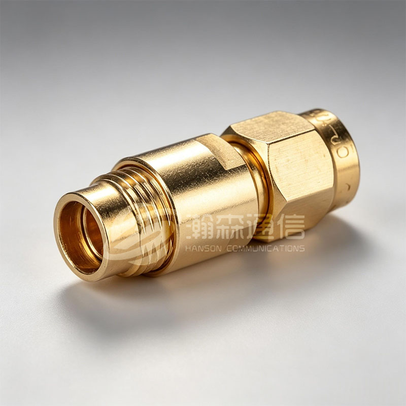
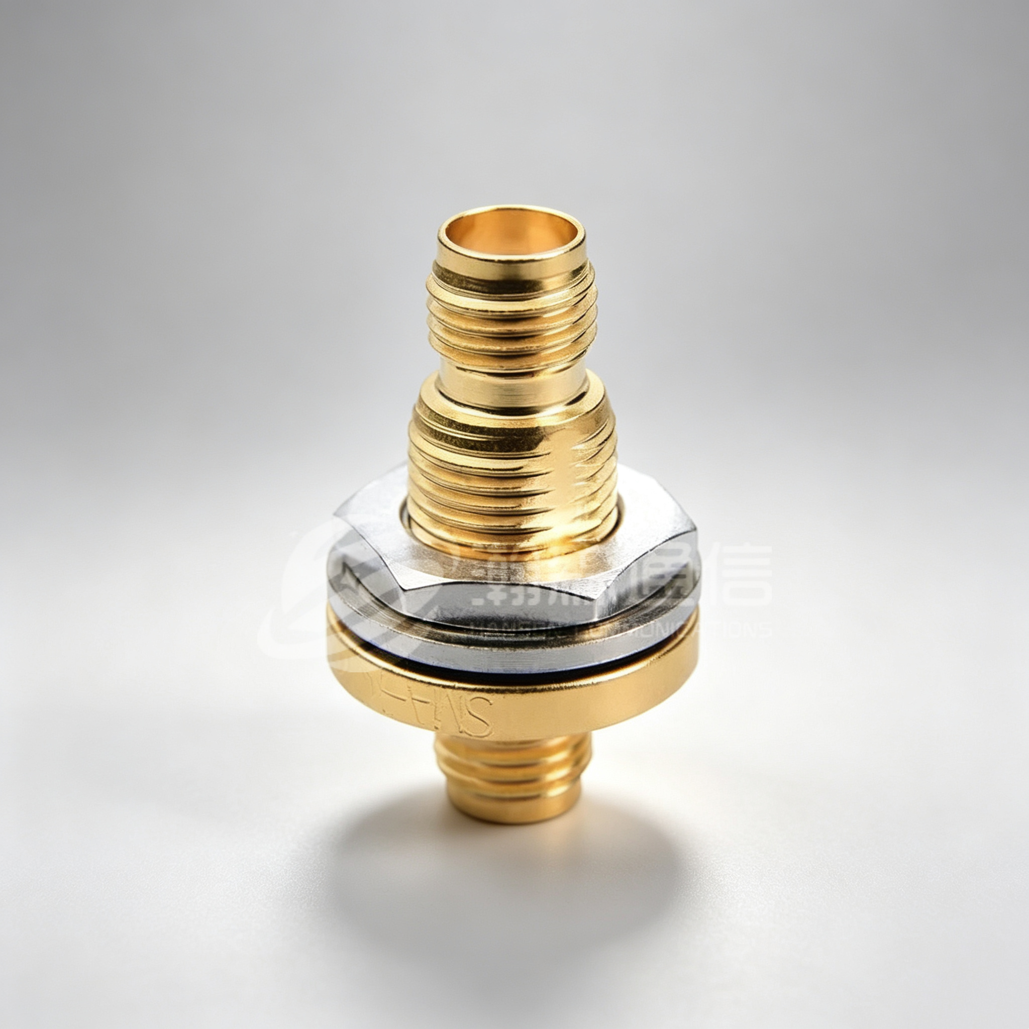
When a compact metric matters — for example, in a dense 5G array — a properly selected SMA connector remains a mature, cost-effective choice. Many manufacturers supply SMA with gold-plated contacts and passivated stainless steel bodies.
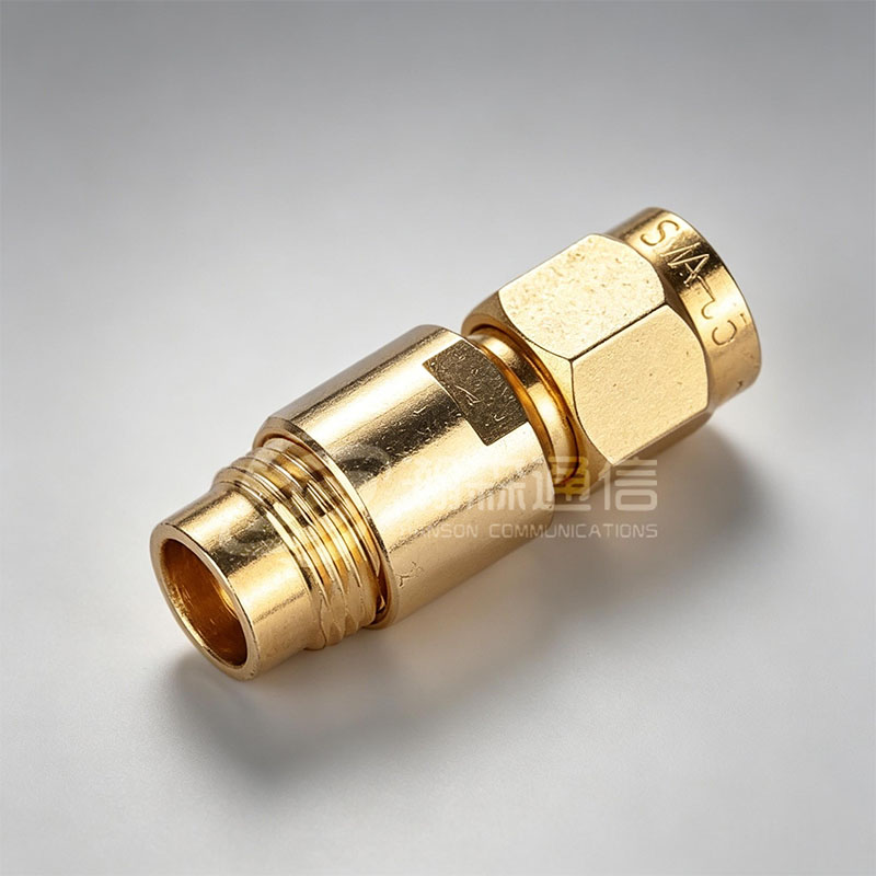 SMA RF Coaxial Connector for Dense 5G ArraysThis mature, threaded SMA connector operates from DC to 26.5 GHz with 50-ohm impedance and gold-plated contacts. Its compact size and proven reliability make it a cost-effective choice for space-constrained microwave systems.View Product →
Environmental and Lifetime Factors
If the system will operate in a humid or corrosive environment, consider hermetically sealed interfaces. SMP and SMPM are available in sealed versions that block moisture and contamination. For high-altitude or vacuum applications, a glass-sealed feedthrough is required to maintain a pressure boundary. In normal indoor equipment, a standard connector can be sufficient, but check the temperature range of the dielectric material (typically PTFE, rated from -65°C to +165°C).
For millimeter-wave research or instrumentation, a higher-cost 1.85 mm connector can be justified by its repeatable performance and lower dispersion compared with SMA.
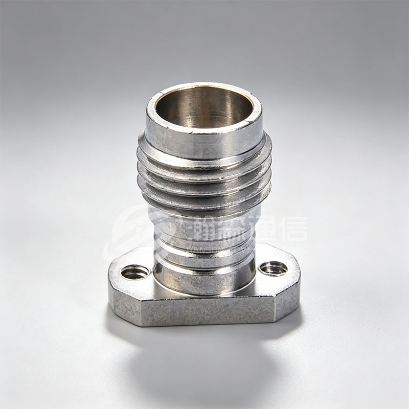 1.85mm High-Frequency RF Coaxial Connector for Millimeter-Wave UseOffering DC to 67 GHz coverage with low dispersion and repeatable performance, this compact connector suits precision instrumentation and research applications where signal integrity at millimeter-wave frequencies is critical.View Product →
Real-World Applications and Environment Considerations
Miniature RF connectors appear in four major areas:
- 5G/6G base stations and antenna arrays: SMP and SMPM connectors support blind-mate board-to-board connections in active antenna units, minimizing cable harnesses.
- Test and measurement equipment: 2.4 mm and 1.85 mm connectors provide mode-free operation up to 50 and 67 GHz, enabling accurate S-parameter measurements.
- Aerospace and defense electronics: Hermetically sealed SMP/SMPM connectors protect sensitive modules from altitude and humidity changes.
- Medical instruments: Miniature connectors help keep probes small and lightweight while carrying high-frequency signals for imaging.
 Hermetically Sealed SMP Connector for Harsh EnvironmentsUsing Kovar alloy and high-temperature glass dielectric, this SMP connector provides a hermetic barrier against moisture and gas. Its small, lightweight design supports dense mounting in sealed or high-reliability applications.View Product →
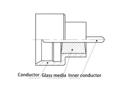
In harsh environments, sealing is not an afterthought. A hermetically sealed connector uses glass or ceramic to isolate the center conductor from the housing, preventing gas and moisture migration. This is why the same connector series can have very different reliability ratings depending on whether the glass-to-metal seal is included.
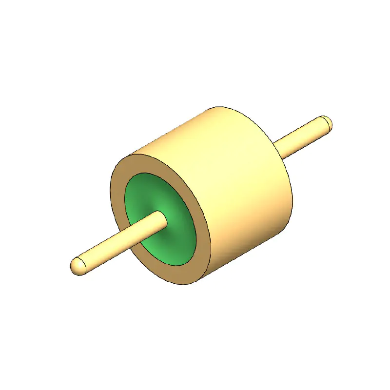
Figure 2: Simplified isometric view of a miniature RF connector showing the inner conductor, dielectric, and outer shell.
In any of these environments, test the connector with the actual cable or PCB launch. A connector that works well on a bench with a semi-rigid cable may perform differently on a flexible cable because of ground current leakage and field geometry.
Sourcing and Quality Risks
Buying miniature RF connectors is not the same as buying hardware from a catalog. Small variations in plating thickness, center-pin chamfer, and shell hardness directly affect mating durability and intermodulation performance. A typical failure mode in low-cost connectors is brass bodies with thin gold over nickel; after repeated mating cycles, the gold wears and the nickel oxidizes, increasing contact resistance.
When evaluating a supplier, look for evidence of process control: ISO 9001, in-house machining and plating capability, and documented inspection reports. A manufacturer with its own workshop can control tolerances better than a trading company. For example, Ningbo Hanson Communication Technology, a manufacturer in Ningbo, China, states that it operates machining, plating, and assembly workshops and holds over 45 patents. If the connector must survive wash-down or salt fog, ask specifically about the plating thickness and whether the seal is tested with helium mass spectrometry.
Ask for a "connector-to-connector" VSWR test report at your operating frequency, not just a datasheet. A report generated with a matched cable and a proper torque will reveal assembly consistency. Even a simple batch history can help you spot variations in plating or machining.
Cleaning and maintenance also matter after installation. Dust and flux residue can change the insertion loss of miniature connectors because the small air gap around the dielectric is more sensitive to contamination. Periodic inspection is recommended for high-reliability modules.
Frequently Asked Questions
What is the difference between SMA, SMP, and SMPM connectors?
SMA is a threaded, semi-precision connector rated up to 18/27 GHz. SMP uses a snap-on interface for compact blind-mate connections up to 40 GHz. SMPM is smaller than SMP, snap-on, and rated up to 65 GHz for millimeter-wave modules.
Are miniature RF connectors always 50 ohms?
Most miniature RF connectors are 50 Ω, but 75 Ω versions exist for video and broadcasting. You cannot mix 50 Ω and 75 Ω connectors without an adapter; the center pin diameter and dielectric dimensions differ.
Why does VSWR increase when I use a miniature connector above its rated frequency?
Above the rated frequency, higher-order modes begin to propagate in the connector cavity. The impedance is no longer uniform, so reflections increase. Using a connector with a higher frequency ceiling (e.g., 2.4 mm instead of SMA) avoids this issue.
Can I solder a miniature RF connector directly to a PCB?
Yes, but the PCB launch must be designed carefully. Controlled impedance, ground via spacing, and solder paste volume all affect return loss. For frequencies above 10 GHz, launch simulation is recommended.
Do hermetically sealed RF connectors need special handling?
Sealed connectors can handle external pressure and humidity, but avoid exceeding the rated torque or temperature during soldering. The glass seal may crack if heated unevenly.
How do I extend the life of a miniature RF connector?
Use the correct torque wrench for threaded types, keep mating surfaces clean, and minimize the number of mating cycles. For snap-on types, inspect the retaining fingers periodically for fatigue.

Looking For Business Opportunity?
Request for a call today
-

+86-15715730755
-

-

No. 1, Longcao Road, Dongqian Lake Tourism Resort Industrial Zone, Yinzhou District, Ningbo City, Zhejiang, China.
Message
Copyright © Ningbo Hanson Communication Technology Co., Ltd.
