


 English
 русский
Industry News
 Home / News / Industry News / RG Cable Types Explained: Impedance, Shielding, and Real RF Performance
RG Cable Types Explained: Impedance, Shielding, and Real RF Performance
 2026.10.21
 Industry News
Swap a short RG-58 jumper for an RG-174 jumper in a 2.4 GHz measurement chain and the received level drops by roughly 1.5 dB. Nothing is faulty: the thinner cable simply carries more loss per metre at that frequency. The RG number printed on the jacket is the most visible label on a coaxial cable and the least useful one on its own.
The short answer: RG designations are legacy MIL-17 identifiers that fix a nominal size and impedance family, not a performance grade. Two reels both sold as RG-58 can differ in braid coverage, dielectric, velocity of propagation and jacket compound, and therefore in attenuation, shielding and temperature rating.
- Confirm impedance first: 50 Ω for radios, test gear and antennas; 75 Ω for video, CATV and satellite IF.
- Then read the construction: dielectric material, shield style and coverage, jacket compound.
- Finally check attenuation at your operating frequency, not a "DC to 1 GHz" headline.
Content
- 1 What an RG number does and does not tell you
- 2 Impedance first: 50 Ω and 75 Ω do not mix
- 3 The four layers that set loss, shielding and service life
- 4 Attenuation by type: diameter beats marketing language
- 5 Matching the type to the job
- 6 Connectors and assemblies take the last few decibels
- 7 A short procurement checklist
- 8 RG cable types: common questions
What an RG number does and does not tell you
The RG prefix comes from the "Radio Guide" designations used during the Second World War and later standardised in MIL-C-17, today MIL-DTL-17. The base number fixes a nominal construction, while the slash suffix fixes a revision. RG-58A/U, RG-58C/U and a generic "RG-58" reel are not interchangeable inside a link budget, because conductor stranding, dielectric compound and braid coverage changed between revisions.
| Type | Impedance | Dielectric | Shield | Typical O.D. | Where it fits |
|---|---|---|---|---|---|
| RG-6 | 75 Ω | Foamed PE | Foil + braid | 6.9 mm | Satellite and CATV drops |
| RG-11 | 75 Ω | Foamed PE | Foil + braid | 10.3 mm | Long 75 Ω trunk runs |
| RG-59 | 75 Ω | Solid PE | Single braid | 6.1 mm | Short legacy video, CCTV |
| RG-58 | 50 Ω | Solid PE | Single braid | 4.95 mm | HF/VHF jumpers, legacy kits |
| RG-8X | 50 Ω | Foamed PE | Single braid | 6.1 mm | Amateur HF, budget routes |
| RG-213 | 50 Ω | Solid PE | Single braid | 10.3 mm | VHF/UHF antenna feeders |
| RG-142 | 50 Ω | Solid PTFE | Double braid | 4.95 mm | Bench work, high-temperature routes |
| RG-316 | 50 Ω | Solid PTFE | Single or double braid | 2.5 mm | Tight bends, internal wiring |
| RG-174 | 50 Ω | Solid PE | Single braid | 2.5 mm | Short low-frequency jumpers |
Treat the table as a starting point, not a specification. A low-cost RG-6 with light braid coverage and a drop-grade RG-6 with foil plus dense braid share the same RG label and behave very differently in a shield-effectiveness or return-loss test.
Impedance first: 50 Ω and 75 Ω do not mix
A 50 Ω connector on 75 Ω cable usually threads on without complaint, which is exactly how the mistake spreads through a rack. The junction is a step discontinuity with a reflection coefficient of 0.2:
1.5:1VSWR at a 50/75 Ω junction
14 dBReturn loss, same junction
0.18 dBMismatch loss per transition
That 0.18 dB looks harmless on a receive-only link, but reflections are not only loss. They shift phase, they wreck return-loss measurements on a bench, and on duplex systems they add to the error-vector budget. Keep one impedance from radio to antenna, adapters and bulkheads included.
The four layers that set loss, shielding and service life
Every RG cable is the same stack of four parts. What changes between types is the material and thickness of each layer.
Center conductor and dielectric
The center conductor carries the signal, and at high frequency the current crowds to its surface, which is why precision cables use silver-plated copper rather than plain copper. The dielectric sets both impedance and velocity of propagation (Vp), the number that decides whether two cables of "the same" type stay in phase across a multi-channel run.
Typical Vp values; foamed PE commonly falls between 78% and 84% depending on the foaming process.
Solid polyethylene is cheap and stable but slows the wave to about 66% of light speed. Foamed PE raises Vp to roughly 80% and cuts loss, at the price of mechanical sensitivity. PTFE holds its properties to around 200 °C and is the default for lab and aerospace work.
Shield and jacket
A single braid at 95% coverage is the workhorse. Double braid improves transfer impedance and flex life, while foil plus braid reaches 100% coverage at low frequencies but is stiffer and awkward to terminate in the field. Jacket choice is a temperature and chemical question: PVC for indoor and bench use, FEP or PTFE when the cable runs near a power amplifier or a hot engine bay.
Attenuation by type: diameter beats marketing language
Published typical values; small-diameter types (orange) are highlighted because they dominate the loss budget in short jumpers.
Two rules explain the chart. Loss scales roughly with the square root of frequency, so doubling frequency adds about 41% more attenuation. And loss falls as the dielectric diameter grows, which is why a 10.3 mm RG-213 beats a 4.95 mm RG-58 by more than 8 dB per 100 m at 100 MHz.
Put that on a real run. Twenty metres of RG-58 costs about 3 dB at 100 MHz and roughly 6.4 dB at 400 MHz, so at UHF half the transmit power is already gone before the antenna sees anything. The same run in RG-213 loses about 1.3 dB at 100 MHz.
Matching the type to the job
Broadcast and video distribution
RG-6 and RG-11 carry 75 Ω signals with foil-plus-braid shielding and F or 75 Ω BNC terminations. Reserve RG-59 for short patch runs inside a rack, where its higher loss does not accumulate.
Bench and test
RG-142, RG-316 and RG-400 use PTFE dielectric and double braid, so phase stays stable when a cable warms up. Short runs keep loss workable well above 6 GHz, where the dielectric and shield quality matter more than diameter.
Antenna and repeater feeders
RG-213 and RG-8X are the usual 50 Ω outdoor choices with N-type connectors. Past roughly 30 m, the loss advantage of a larger low-loss assembly is worth more than the price gap at purchase.
Tight routes and internal jumpers
RG-174 and RG-316 squeeze through a 2.5 mm jacket with a bend radius of a few millimetres. Accept 19 to 29 dB per 100 m at 100 MHz as the price of that flexibility and keep those runs short.
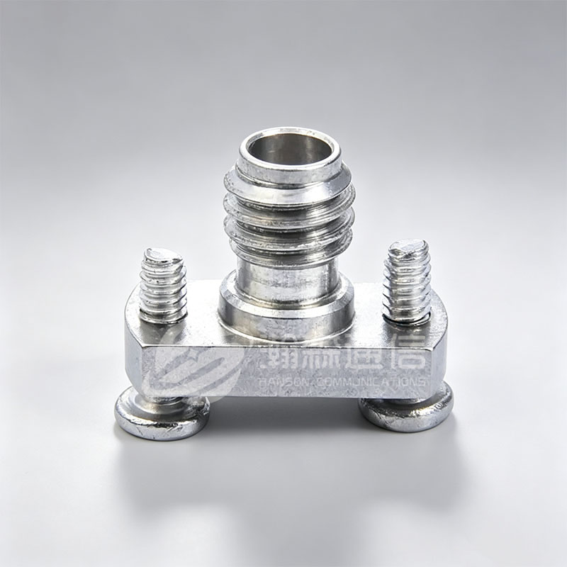
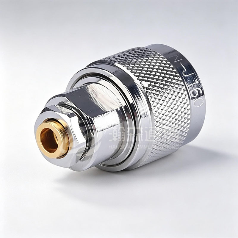 N-Type RF Coaxial Connector SeriesThreaded 50Ω/75Ω connectors, with 50Ω coverage to 18 GHz, relevant when termination quality affects return loss, shield continuity, and passive intermodulation.View Product →
Connectors and assemblies take the last few decibels
A clean RG-213 feeder with a poorly soldered N connector will underperform a short RG-58 link terminated in a factory-built assembly. Termination quality shows up as return loss, as shield continuity, and on duplex sites as passive intermodulation.
Two construction details matter more than the label on the jacket. Crimp versus solder decides long-term reliability under vibration, and for multi-channel feeds, phase matching to a few degrees keeps phased arrays and beamforming coherent. Assemblies built and tested as one unit remove most of those field variables; this overview of how RF cable assemblies are built walks through the termination and test steps that set the final numbers.
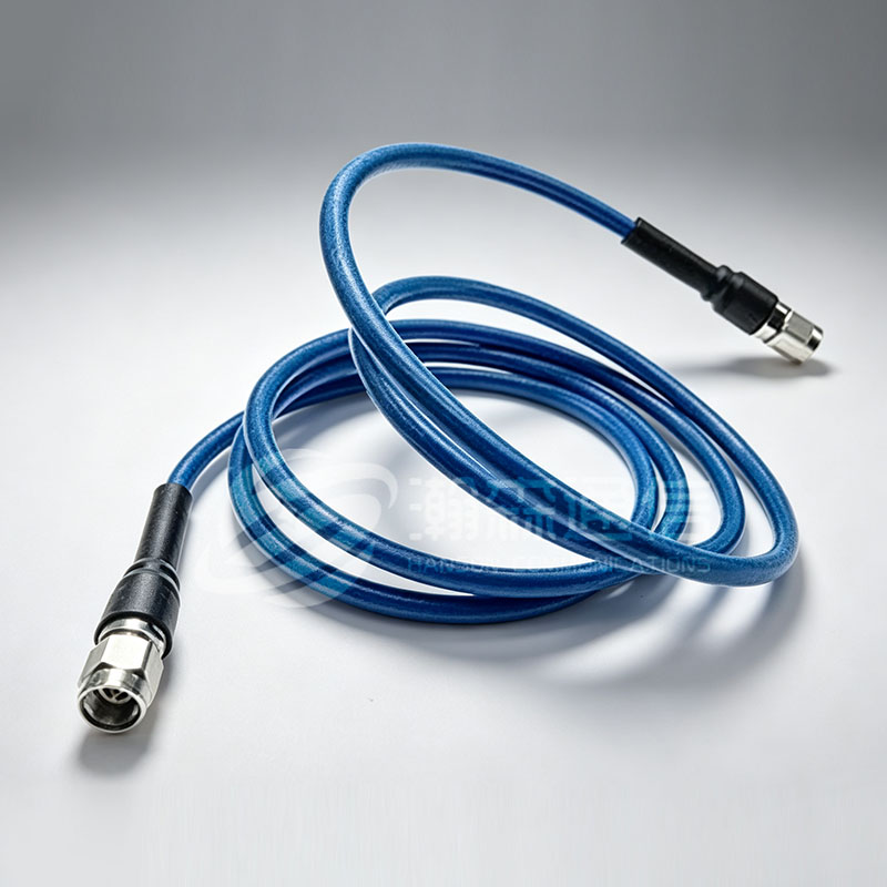 Steady Phase Ultra Low-Loss Flexible Cable AssemblyStable-phase, low-loss flexible assembly for high-frequency links where phase matching and termination quality matter across SMA, N-type, and TNC connectors.View Product →
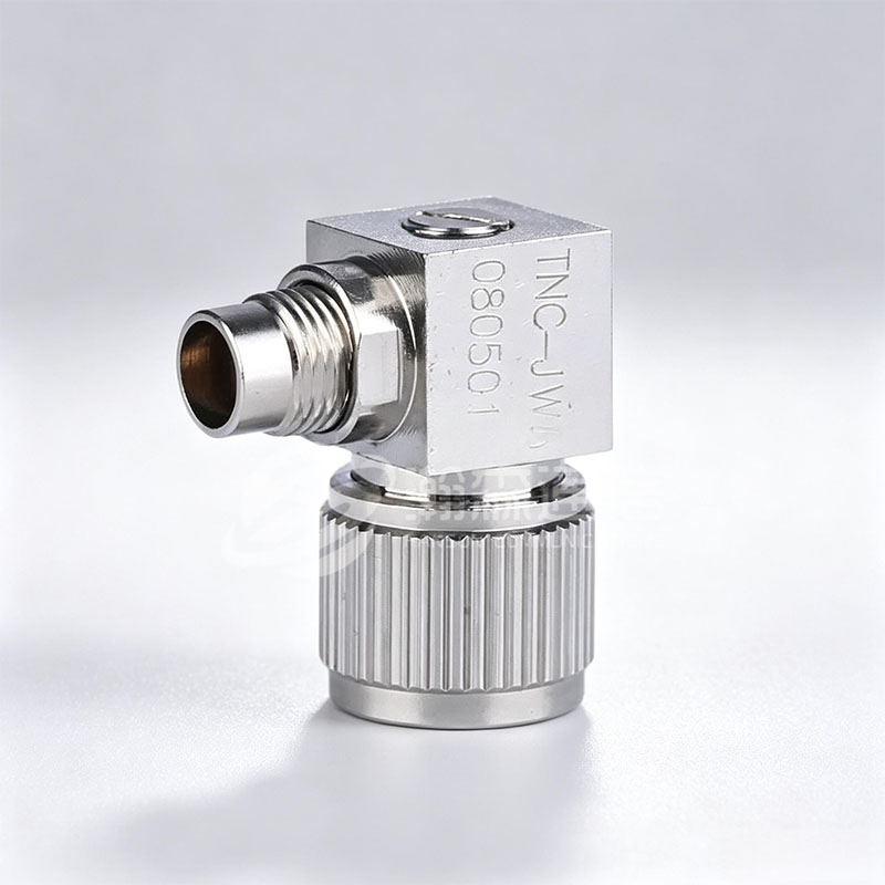
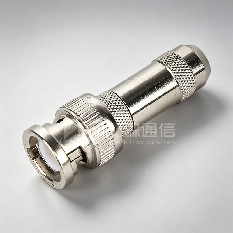
Interface choice follows frequency and mating standard: BNC for quick patching below 4 GHz, SMA for compact microwave work and dense rack panels, N-type for outdoor feeders and weatherproofing, TNC for vibration-prone connections. Each adds its own small reflection, and a chain of three adapters can cost more return loss than the cable itself.
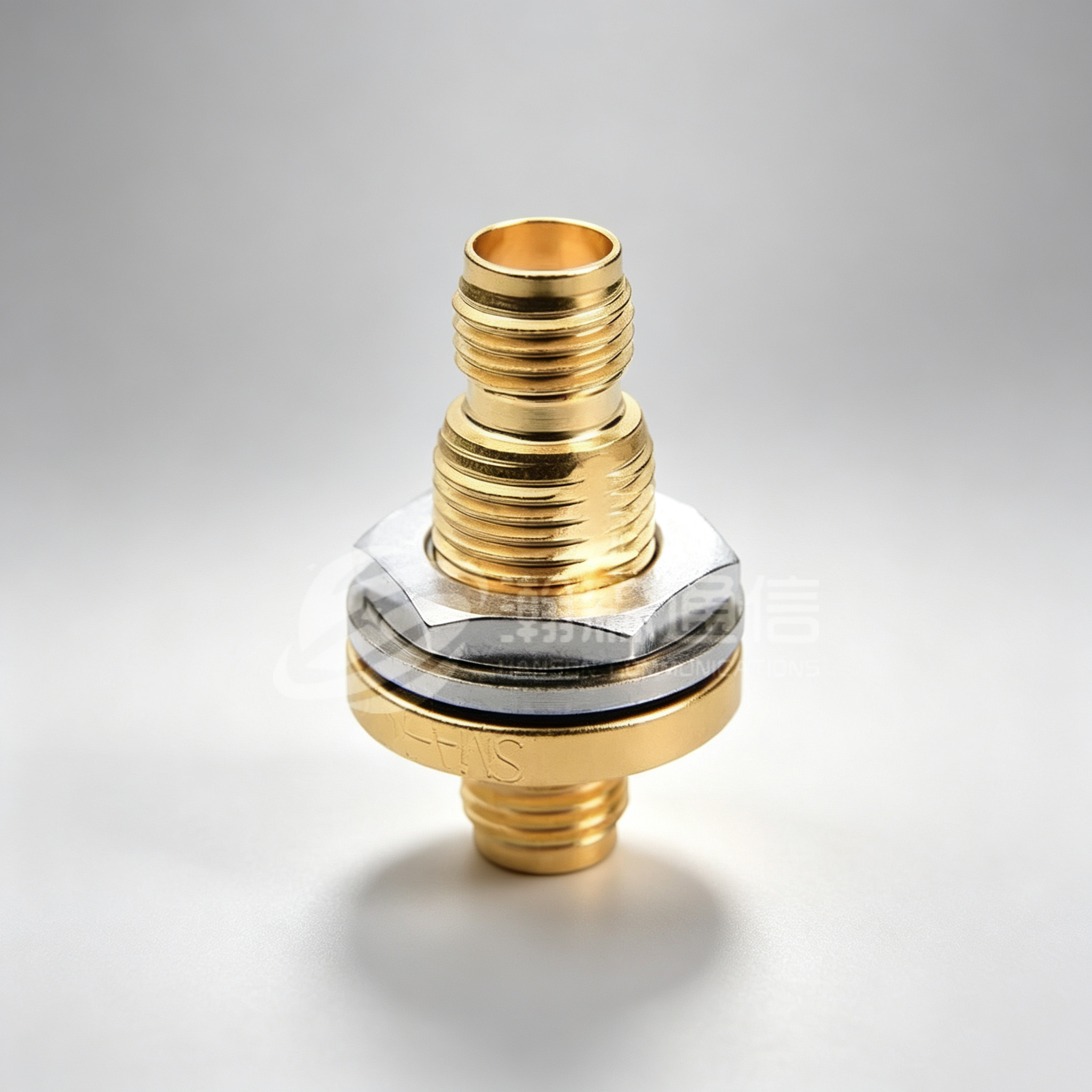
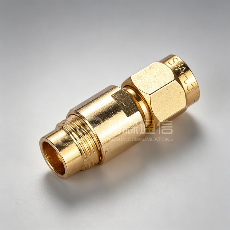 SMA RF Coaxial Connector SeriesCompact 50Ω threaded connectors rated to 26.5 GHz, suited to microwave work and dense rack panels where adapter reflections add up.View Product →
Where the budget is tight, compare a standard RG type against a purpose-built alternative before ordering reels. Low-loss cable assemblies using foamed or PTFE dielectrics often buy back several dB in the same footprint, and a short jumper upgrade frequently solves an interference problem that no amount of connector re-torquing will fix.
A short procurement checklist
- Impedance and interface confirmed at both ends, adapters and bulkheads included.
- Attenuation quoted in dB per 100 m at the highest operating frequency, taken from a datasheet rather than a catalogue headline.
- Shield specification stated explicitly: braid coverage percentage, single or double braid, foil where relevant.
- Temperature and jacket: PVC below about 80 °C, FEP or PTFE where soldering heat or a power amplifier is nearby.
- Bend radius and pull strength checked against the actual route, not the drawing-board route.
- Vp and phase tolerance defined if more than one cable feeds the same antenna array.
- Test data required per reel or per assembly: insertion loss, return loss, and PIM for duplex sites.
RG cable types: common questions
What is the difference between RG-6 and RG-59?
Both are 75 Ω. RG-6 uses a larger conductor and foamed dielectric with foil-plus-braid shielding, so it loses less per metre and suits satellite and CATV drops. RG-59 is thinner, single braided, and belongs in short legacy video runs.
Is RG-58 the same as RG-58A/U or RG-58C/U?
No. The suffix marks a different controlled construction: stranding, dielectric and braid vary between revisions. For a link budget, use the attenuation figure for the exact variant and ask for the datasheet.
Can I fit a 50 Ω N-type connector on 75 Ω RG-6?
Mechanically it often fits, but the impedance step creates a reflection of about 14 dB return loss and VSWR 1.5:1 before the connector's own limit is counted. Keep 75 Ω connectors on 75 Ω cable.
Which RG cable is best for 2.4 GHz or 5.8 GHz?
At those frequencies loss per metre dominates. PTFE types such as RG-142 or RG-316 suit short lab runs, while long runs deserve a larger low-loss assembly rather than any RG-58 or RG-174 reel.
Where do RG-174 and RG-316 belong?
In short internal jumpers, tight bend routes and low-power signal paths. RG-174 is the cheapest and lossiest option; RG-316 adds PTFE dielectric and a higher temperature rating at a similar diameter.
How much loss does 10 m of RG-58 add at 400 MHz?
Roughly 3 dB. Published figures place RG-58 near 32 dB per 100 m at 400 MHz, so 10 m costs about half the transmit power. Loss rises with the square root of frequency, so doubling frequency adds about 41%.
Looking For Business Opportunity?
Request for a call today
-

+86-15715730755
-

-

No. 1, Longcao Road, Dongqian Lake Tourism Resort Industrial Zone, Yinzhou District, Ningbo City, Zhejiang, China.
Message
Copyright © Ningbo Hanson Communication Technology Co., Ltd.
