


 English
 русский
Industry News
 Home / News / Industry News / RF Coaxial Connector Types: SMA, N-Type, BNC, Precision and Sealed Options
RF Coaxial Connector Types: SMA, N-Type, BNC, Precision and Sealed Options
 2026.11.18
 Industry News
Choosing an RF coaxial connector by physical size alone can create a costly mismatch. A part may mate with the cable and still fail on frequency, return loss, sealing, or mating durability. The practical starting point is the interface standard, then the electrical and mechanical requirements around it. The main RF coaxial connector types below cover most signal-chain decisions, from benchtop test to outdoor base-station hardware and millimeter-wave modules.
No single interface is best for every design. SMA may be ideal in a test fixture and unnecessary in a video panel. N-Type may suit an outdoor antenna and be too large for a dense module. The useful question is not “Which connector is strongest?” but “Which interface matches the frequency, cable, environment, and assembly method?”
Content
- 1 Start With the Interface, Not the Appearance
- 2 SMA, TNC, and BNC: Workhorse Threaded and Bayonet Types
- 3 N-Type Connectors for Outdoor and High-Power RF
- 4 Precision Millimeter-Wave Types: 2.4 mm, 1.85 mm, and 1.0 mm
- 5 Sealed and Blind-Mate Options for Harsh or Dense Systems
- 6 What to Check Before You Specify a Connector Type
- 7 How Connector Type Affects Cost and Lead Time
- 8 Frequently Asked Questions
- 8.1 Q1. What are the most common RF coaxial connector types?
- 8.2 Q2. How do I choose between 50-ohm and 75-ohm connectors?
- 8.3 Q3. Is SMA better than BNC?
- 8.4 Q4. When should I use an N-Type connector?
- 8.5 Q5. What is the difference between 2.4 mm and 1.85 mm connectors?
- 8.6 Q6. Can you supply custom or OEM RF connector assemblies?
Start With the Interface, Not the Appearance
RF connectors are not interchangeable even when they look similar. An SMA and a 3.5 mm connector may appear close in scale, but their dielectric, tolerances, and frequency behavior differ. Before comparing vendors, define impedance, maximum operating frequency, coupling method, cable or board attachment, environmental exposure, and expected mating cycles. The table below gives a practical baseline.
| Type | Coupling | Impedance | Typical frequency range | Typical use |
|---|---|---|---|---|
| SMA | Threaded, 1/4-36 | 50 Ω | DC–18 GHz typical; precision variants higher | Test, wireless, instrumentation, antennas |
| N-Type | Threaded | 50 Ω; 75 Ω variants | DC–11 GHz standard; to 18 GHz in some designs | Outdoor antennas, base stations, rugged cable runs |
| TNC | Threaded | 50 Ω; 75 Ω variants | DC–11 GHz typical | Mobile radio, vibration-prone equipment |
| BNC | Bayonet | 50 Ω; 75 Ω variants | DC–4 GHz typical | Laboratory, video, general test |
| 2.4 mm | Threaded precision | 50 Ω | DC–50 GHz | Millimeter-wave test, high-frequency modules |
| 1.85 mm | Threaded precision | 50 Ω | DC–67 GHz | High-frequency test and instrumentation |
| 1.0 mm | Threaded precision | 50 Ω | DC–110 GHz | Wafer probing and sub-THz research |
| SMP / SMPM | Push-on or blind mate | 50 Ω | SMP to 40 GHz; SMPM to 65 GHz | Dense modules and board-to-board assemblies |
Use these values as selection ranges, not guaranteed limits for every product. Actual performance depends on the cable, adapter, termination, plating, and test method. A 50-ohm connector used in a 75-ohm video path, for example, will create a mismatch even if the threads fit.
SMA, TNC, and BNC: Workhorse Threaded and Bayonet Types
These three families cover much of the general RF market. The RF coaxial connector portfolio includes these interfaces and other standard and precision options.
SMA connectors
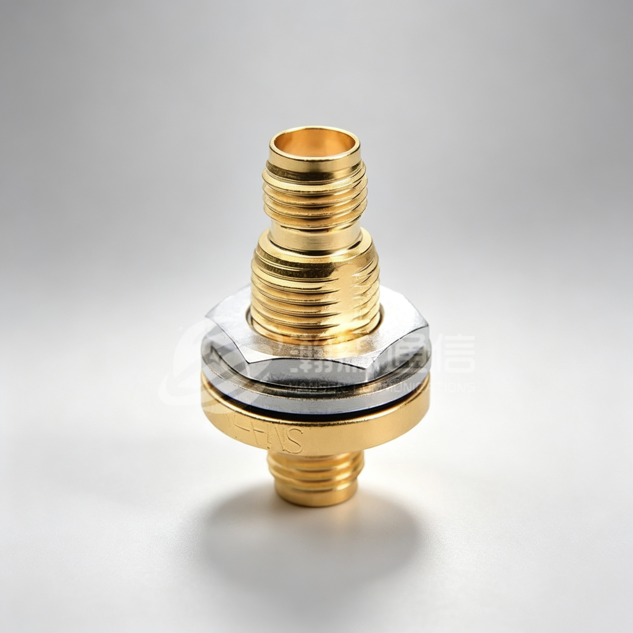
SMA is a compact 50-ohm threaded interface widely used in test equipment, wireless modules, antennas, and instrumentation. Standard SMA designs are commonly specified to 18 GHz, while precision variants may reach higher frequencies. The threaded coupling provides stable contact, but the small threads and center pin require controlled torque. Over-tightening can damage the dielectric or distort the interface. For repeated lab use, a torque wrench and inspection routine are more valuable than a lower unit price.
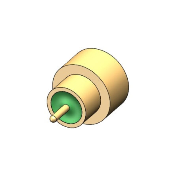
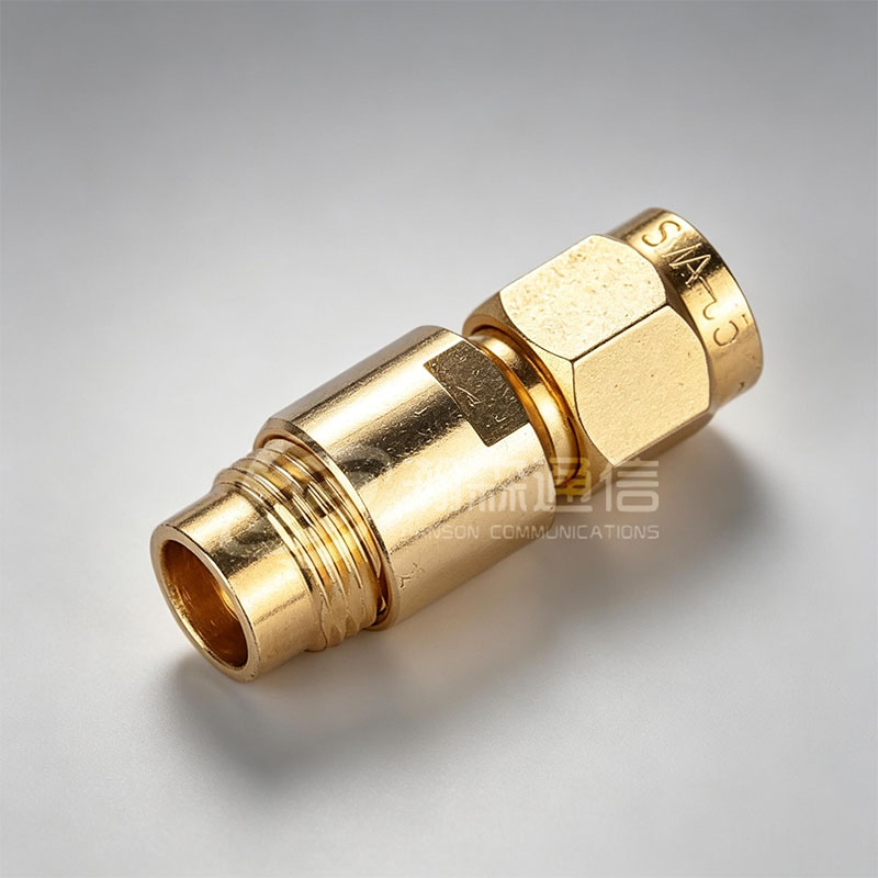 SMA RF Coaxial Connector SeriesThreaded 50-ohm SMA series specified to 26.5 GHz with 500 mating cycles, suited to test equipment, wireless modules, antennas, and instrumentation.View Product →
TNC and BNC connectors
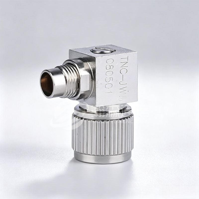
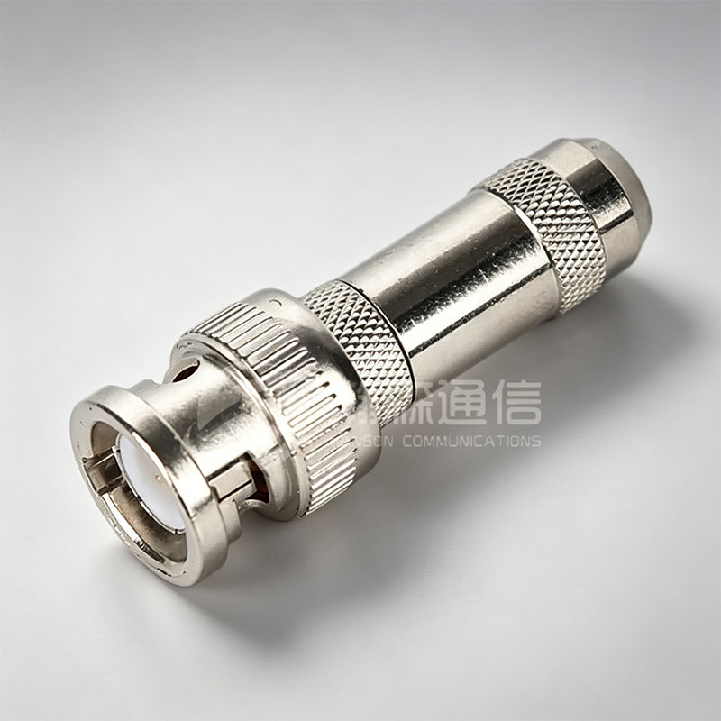
TNC uses a threaded coupling similar in size to BNC and is often chosen where vibration could loosen a bayonet. It is common in mobile radio, instrumentation, and antenna runs, with typical operation to 11 GHz depending on design. BNC uses a bayonet latch for fast mating and is common in laboratory, video, and general test setups. Most BNC designs are useful to about 4 GHz. BNC is convenient, not precision. For high-frequency measurements, a threaded precision connector is usually the better choice.
N-Type Connectors for Outdoor and High-Power RF
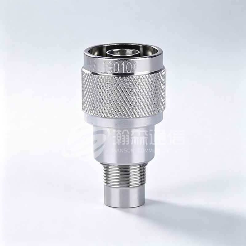
N-Type is a larger threaded 50-ohm interface built for rugged coaxial cable, antennas, base-station equipment, and outdoor enclosures. Standard N-Type designs are typically specified to 11 GHz, with some high-performance versions reaching 18 GHz. The larger geometry handles cable sizes and power levels that small connectors cannot.
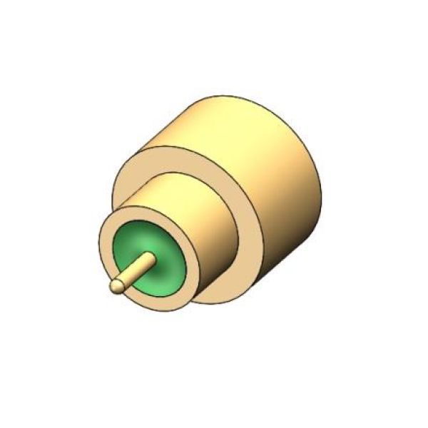
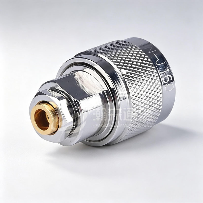 N-Type RF Coaxial Connector SeriesRugged threaded N-Type series available in 50Ω and 75Ω, with 50Ω designs specified to 18 GHz for antennas and outdoor coaxial runs.View Product →
In outdoor use, the connector body is only part of the system. Cable entry sealing, gasket condition, plating, and proper weatherproofing determine whether moisture reaches the interface. A nickel-plated body may suit general outdoor use; gold-plated center contacts are common where low contact resistance is important. Inspect threads and sealing surfaces before assembly, and follow the cable manufacturer’s termination dimensions. Because N-Type is often used at remote sites, a damaged thread or loose cable gland can be expensive to correct. Specify the cable type, assembly method, and sealing accessory together, not as separate line items.
Precision Millimeter-Wave Types: 2.4 mm, 1.85 mm, and 1.0 mm
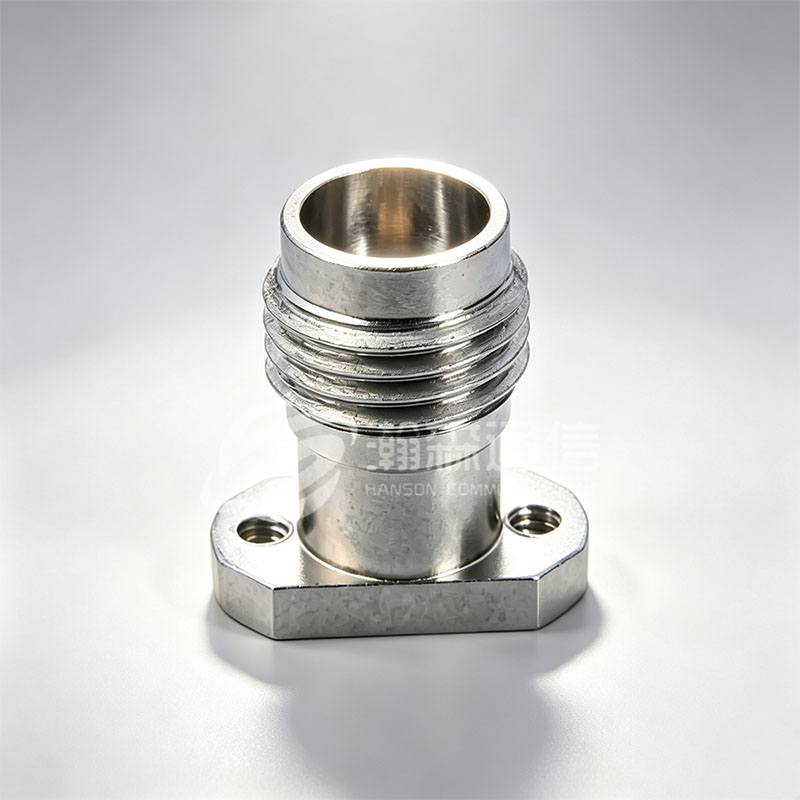
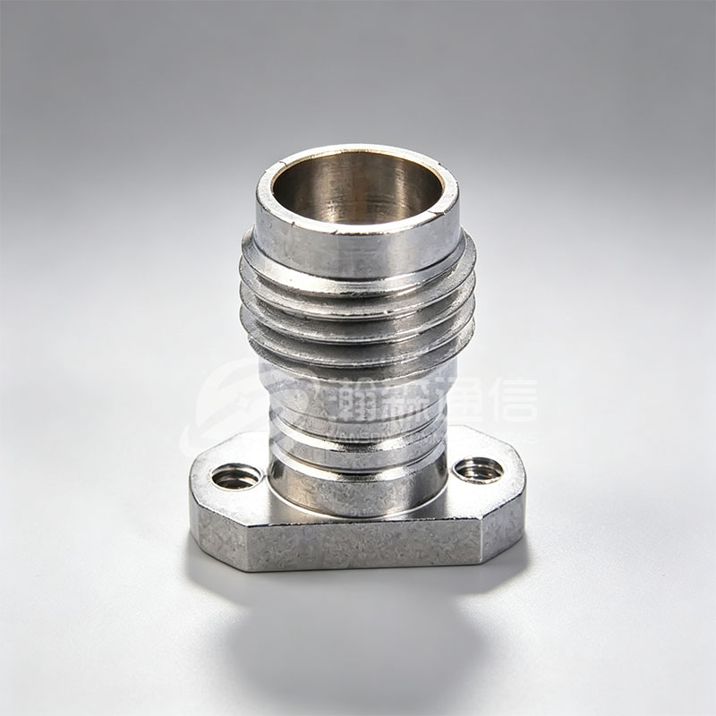
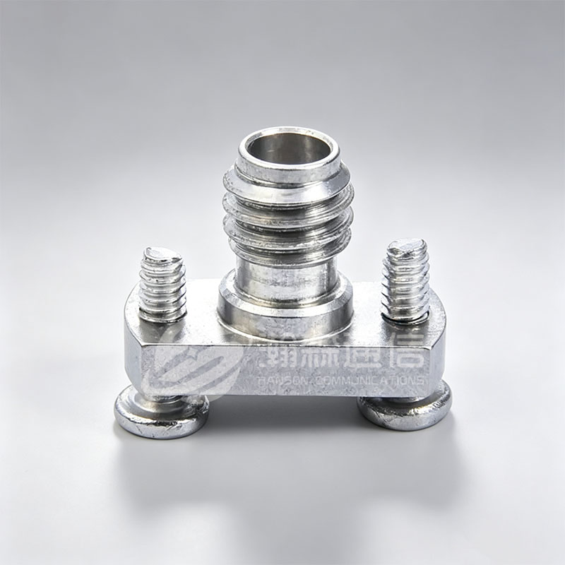
Above about 26 GHz, connector selection becomes a tolerance exercise. Precision air-dielectric interfaces use tighter center-pin alignment, controlled bore diameters, and materials selected for dimensional stability. The 2.4 mm interface is commonly used to 50 GHz, 1.85 mm to 67 GHz, and 1.0 mm to 110 GHz. These connectors appear in test fixtures, wafer probing, radar modules, and high-frequency research.
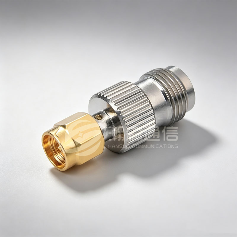
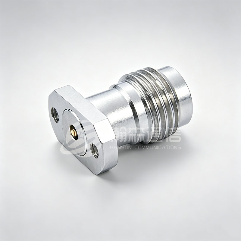 2.4 mm Precision RF Coaxial Connector50-ohm 2.4 mm connector specified to 50 GHz with VSWR ≤1.35, intended for precision test, measurement, and high-frequency signal connections.View Product →
They are not general-purpose field connectors. Small amounts of contamination, a burr on the center pin, or an incorrect mating torque can raise insertion loss and return loss. Keep protective caps in place, clean with the correct tools, and verify mating compatibility before connecting two precision interfaces. Precision connectors also demand a different purchasing standard. Ask for interface dimensions, material and plating details, and inspection records. For assembly guidance, review proper installation of RF coaxial connectors before production.
Sealed and Blind-Mate Options for Harsh or Dense Systems
SMP and SMPM connectors use push-on or blind-mate designs for dense board-to-board and module-to-module connections. SMP is typically used to about 40 GHz and SMPM to about 65 GHz, depending on design and cable. Their small size and float tolerance help in multi-port assemblies where several connectors must mate at once.
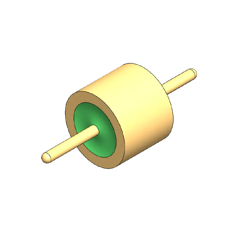
Where moisture, pressure, or vacuum protection is required, hermetic versions use glass-to-metal seals or similar construction. A hermetically sealed connector is not automatically a waterproof cable assembly; the cable entry and housing interface still need sealing. Check leak rate, temperature range, and mating style against the actual environment. A sealed interface may solve a pressure boundary problem while leaving the cable gland as the weak point.
What to Check Before You Specify a Connector Type
Electrical fit
Confirm characteristic impedance, frequency range, maximum VSWR or insertion loss target, and power handling. A connector that is rated to a frequency may still be unsuitable if the cable or adapter creates a resonance or loss peak. Review the full assembly, not just the interface.
Mechanical and environmental fit
Check coupling style, thread size, mating cycles, cable attachment, panel thickness, temperature, vibration, and sealing. For outdoor or sealed equipment, specify the gasket, O-ring, or glass seal as part of the interface. For high-density racks, blind-mate tolerance and extraction force matter as much as frequency.
Assembly and supplier evaluation
Ask how the connector is terminated: solder, crimp, clamp, or field-replaceable. Confirm plating, dielectric material, contact material, and inspection criteria. A manufacturer that controls machining, plating, and assembly can usually resolve dimensional questions faster than a trader sourcing finished parts. For OEM or custom projects, request drawings, samples, and a defined inspection plan before volume release.
How Connector Type Affects Cost and Lead Time
Cost differences usually come from tolerance, material, plating, and testing, not from the name of the interface. A standard BNC or SMA is produced in high volume and is relatively straightforward. A 1.0 mm precision connector, a hermetically sealed SMPM, or a custom cable assembly with low PIM requirements needs tighter machining, cleaning, and inspection. That changes the production route and the quotation basis.
When comparing suppliers, ask for the same drawing, plating specification, and acceptance criteria. A low piece price can disappear if incoming inspection rejects threads, center-pin location, or plating thickness. For wholesale or OEM orders, clarify MOQ, sample lead time, packaging, and whether custom interfaces or cable assemblies are supported. The connector type should follow the electrical and environmental requirement, not the other way around.
Frequently Asked Questions
Q1. What are the most common RF coaxial connector types?
Common types include SMA, BNC, TNC, N-Type, and precision interfaces such as 2.4 mm, 1.85 mm, and 1.0 mm. SMP and SMPM are common in blind-mate and high-density systems.
Q2. How do I choose between 50-ohm and 75-ohm connectors?
Match the connector to the system impedance. 50-ohm is standard for RF test, wireless, and antennas; 75-ohm is used in video and some telecom paths. Mixing impedances causes reflections.
Q3. Is SMA better than BNC?
Neither is universally better. SMA is threaded and suitable for higher frequency and stable test connections. BNC is faster to mate and common in lower-frequency video and lab work. Choose by frequency, mating cycles, and environment.
Q4. When should I use an N-Type connector?
Use N-Type for outdoor antennas, base-station equipment, and larger coaxial cables where weather resistance and power handling matter. Confirm the frequency range and sealing method for the installation.
Q5. What is the difference between 2.4 mm and 1.85 mm connectors?
Both are precision millimeter-wave interfaces. 2.4 mm is typically used to 50 GHz, while 1.85 mm extends to about 67 GHz. They require careful handling, cleaning, and correct mating torque.
Q6. Can you supply custom or OEM RF connector assemblies?
Custom and OEM requirements can be reviewed against the drawing, cable type, plating, sealing, and test plan. MOQ, lead time, and pricing depend on the interface and assembly. Contact the manufacturer with the application details and required specifications.
For a specification review, share your frequency range, cable or board interface, environmental conditions, and target quantity with the manufacturer. That information is enough to recommend a practical connector type and quotation basis.
Looking For Business Opportunity?
Request for a call today
-

+86-15715730755
-

-

No. 1, Longcao Road, Dongqian Lake Tourism Resort Industrial Zone, Yinzhou District, Ningbo City, Zhejiang, China.
Message
Copyright © Ningbo Hanson Communication Technology Co., Ltd.
