


 English
 русский
Industry News
 Home / News / Industry News / MIL-STD-883 Method 1014: Fine and Gross Leak Testing Explained for Sealed RF Parts
MIL-STD-883 Method 1014: Fine and Gross Leak Testing Explained for Sealed RF Parts
 2026.11.11
 Industry News
A sealed module comes back from the test house with a helium reading of 8 × 10⁻⁸ atm·cc/s and one line of paperwork: "seal test per MIL-STD-883 Method 1014." Engineering wants a verdict, quality wants a signature, and both are staring at a standard that refuses to hand out a single number.
The practical answer first: Method 1014 tells you how to run a seal test, not what your part has to survive. The reject limit comes from the device drawing, from the device specification, or from the volume-based limits inside the method itself, and it shifts with the internal cavity volume of the package. Get that distinction wrong and you either scrap good hardware or ship a leaker with a clean-looking test report.
Content
- 1 What Method 1014 Covers, and What It Leaves to You
- 2 Fine Leak Before Gross Leak: the Sequence Is Not Optional
- 3 Where the Seal Test Meets RF Hardware
- 4 Running the Test Without Burning a Week
- 5 What to Put on the Drawing Before You Order
- 6 Failure Modes and What They Usually Mean
- 7 Frequently Asked Questions
- 7.1 What is the difference between a fine leak test and a gross leak test?
- 7.2 What leak rate does MIL-STD-883 Method 1014 actually require?
- 7.3 Why did my part pass the seal test and still leak in the field?
- 7.4 How long does a helium leak test take?
- 7.5 Does Method 1014 apply to RF connectors and cable assemblies?
- 7.6 What causes a gross leak failure most often?
What Method 1014 Covers, and What It Leaves to You
MIL-STD-883 is the test-method document for microelectronic devices, and Method 1014 is its seal test. It has two halves that barely overlap. Fine leak testing uses a tracer gas, normally helium, to find leaks in the region of roughly 1 × 10⁻⁹ to 1 × 10⁻⁵ atm·cc/s. Gross leak testing picks up everything above about 1 × 10⁻⁵ atm·cc/s, where the leak is large enough to show as a bubble stream or to register as penetrant weight gain.
Fine leak testing is then split into fixed and flexible conditions. A fixed condition applies the same bomb pressure and dwell time to every part, which is reasonable for small cavities and misleading for large ones. The flexible condition lets the laboratory calculate pressure and dwell from the internal volume of the package, so a measured reading can be converted back into a true leak rate.
| Condition | Technique | When it is used |
|---|---|---|
| A1 | Helium fine leak, fixed parameters | Small cavities where a fixed bomb pressure and dwell remain valid |
| A2 | Helium fine leak, flexible parameters | Larger cavities; bomb pressure and soak time are computed from internal volume |
| A3 / A4 | Perfluorocarbon fine leak | Cases where helium exposure is impractical; confirm the lettering against your revision |
| B1 | Gross leak, perfluorocarbon bubble | Visible bubble stream escaping from an immersed part |
| B2 | Gross leak, penetrant weight gain | Gross leaks detected by weighing penetrant taken up by the package |
Every one of these conditions is a technique, not a limit. The limit is a separate decision, and it is the one that decides whether your reading of 8 × 10⁻⁸ is a pass or a rework ticket.
Leak-rate spectrum: which test sees which leak
10⁻⁹10⁻⁸10⁻⁷10⁻⁶10⁻⁵10⁻⁴10⁻³
Indicative detection windows in atm·cc/s; real sensitivity depends on cavity volume, the chosen condition and instrument calibration.
Fine Leak Before Gross Leak: the Sequence Is Not Optional
Method 1014 expects the fine leak test to run before the gross leak test, and the reason is physical. The fluorocarbon used for bubble testing is heavy, wets surfaces, and can sit inside a pinhole long enough to hide it from the mass spectrometer. Run the tests in the wrong order and a leaker can come back looking tight.
Helium testing itself is a two-step process. The part is pressurized in helium so the tracer is forced into any leak, then moved to a mass spectrometer that measures the helium escaping back out. What the detector sees is not the true leak rate. It is a measured rate that depends on how much helium went in, how long the part sat before it was read, and how quickly the gas escapes from the cavity.
Cavity volume is the variable that catches people out. A large cavity absorbs more helium, which pushes the measured rate up, while a tiny cavity gives a weaker signal and needs a tighter threshold to be meaningful. That is why a single blanket leak rate quoted in an email is worth very little.
Schematic: the reject line rises with cavity volume
Schematic trend only, not measured values. Take the actual limits from the table in the current revision of Method 1014 and from your device drawing.
Two parts with identical leaks can therefore produce different readings, and two parts with different leaks can produce the same reading. The flexible condition exists precisely to strip that ambiguity out of the data.
Where the Seal Test Meets RF Hardware
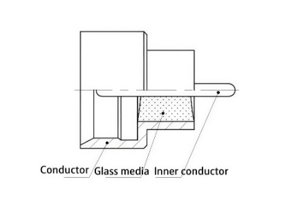
In RF hardware the hermetic barrier is rarely a ceramic lid. More often it is a glass-to-metal seal: a glass bead fused into a metal housing with a centre pin running through it, or a sealed connector body built around a glass insulator that carries the conductor through the wall without losing pressure integrity.
Those parts fail in predictable places. The glass-to-metal interface comes first, because the bond is mechanical and chemical at the same time, and any void, bubble or incomplete wetting becomes a leak path. Plating porosity is second: a pore that reaches the base metal creates a slow leak that a bubble test will never see. The third is the joint itself, where an incomplete solder or weld fillet leaves a gap that opens further under thermal cycling.
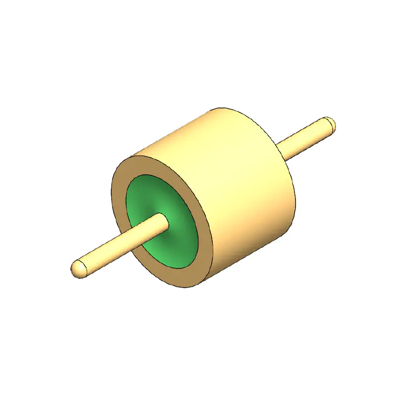
Isometric view: where a sealed feedthrough leaks
Schematic cross-section of a sealed feedthrough: the glass bead and the lid joint are the two usual leak paths.
Cavity volume inside a coaxial feedthrough is small, often a fraction of a cubic centimetre, so the applicable fine leak limit sits at the tight end of the range. A void that would be cosmetic in a large hybrid package can push a small connector body straight out of specification.
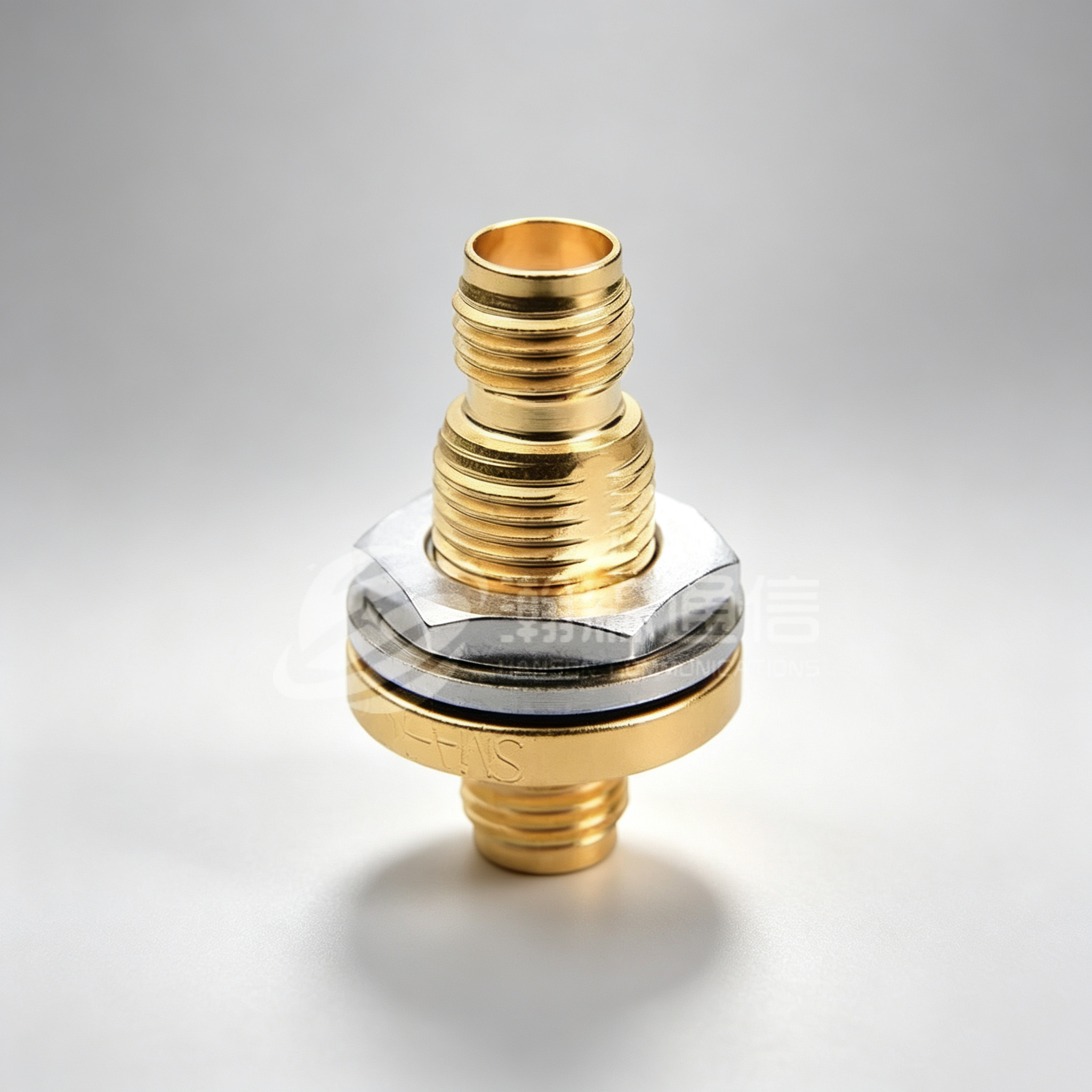
 RF Glass Insulator for Hermetic FeedthroughsGlass-sintered 50Ω RF insulator for compact hermetic feedthroughs, relevant where small cavity volume makes fine leak limits especially tight.View Product →
Running the Test Without Burning a Week
Most seal-test delays come from preparation rather than from the instrument. A few habits keep the schedule intact:
- Bake parts dry before bombing. Moisture inside the cavity competes with helium and produces readings that drift between runs.
- Check the ambient helium background before every batch. A cylinder change or a leaky fitting nearby will lift the baseline and turn good parts into failures.
- Keep the transfer time from bomb to detector short and identical for every sample. Method 1014's conversion assumes a known wait period; a long coffee break invalidates it.
- Verify the mass spectrometer against a calibrated helium leak of known value at the start and end of the shift.
- Handle parts with clean gloves and padded tweezers. A scratch across a glass bead is a new leak path that did not exist when the part was built.
- Record the condition letter, bomb pressure, dwell, wait time and instrument ID on the data sheet, not just the final reading.
That last point matters more than it looks. When a customer disputes a failure two years later, the condition letter and dwell time are usually the only evidence that shows whether the test and the specification actually agreed with each other.
What to Put on the Drawing Before You Order
Purchasing risk on hermetic parts is almost always specification risk. The supplier builds to the drawing, the test house tests to the purchase order, and if those two documents disagree the argument lands in your inbox. Write the following into the drawing and the order:
- The method and condition, for example "seal test per MIL-STD-883 Method 1014, condition A2".
- The reject limit in atm·cc/s, together with the cavity volume it was derived from.
- The test sequence, fine leak before gross leak, plus the sample size and whether it is lot-by-lot or qualification only.
- Any exclusions, such as parts that cannot be exposed to fluorocarbon because of an internal coating or an absorbed material.
- Whether the certificate must include raw readings, calibration data and the instrument background level.
Where the sealed interface is a blind-mate RF joint rather than a flat lid, the seal has to survive mating cycles on top of the pressure differential. That is a different design problem from lid sealing, and it belongs in the specification conversation before the first part is machined.
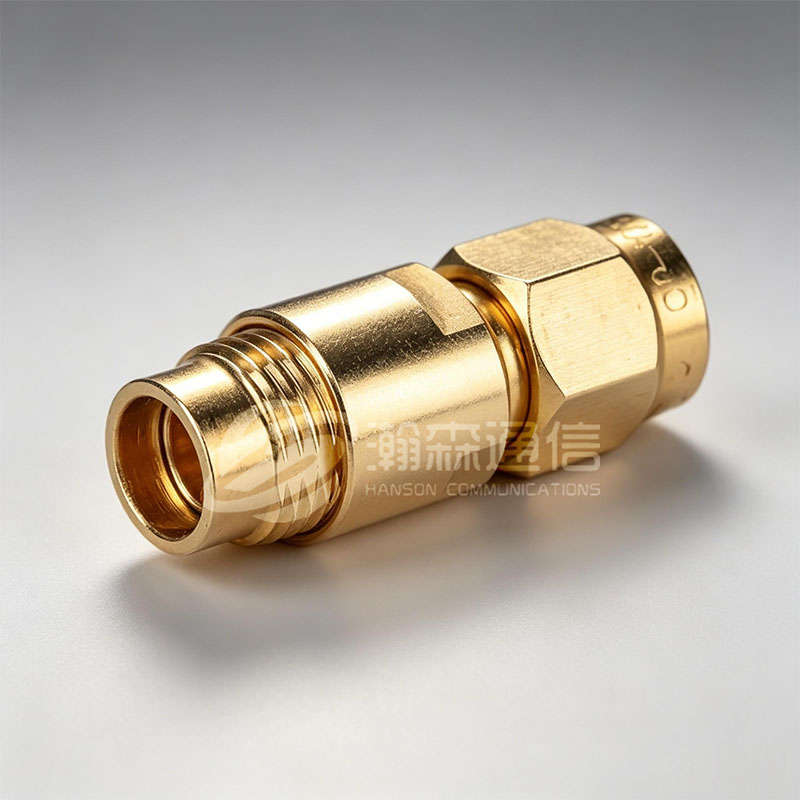
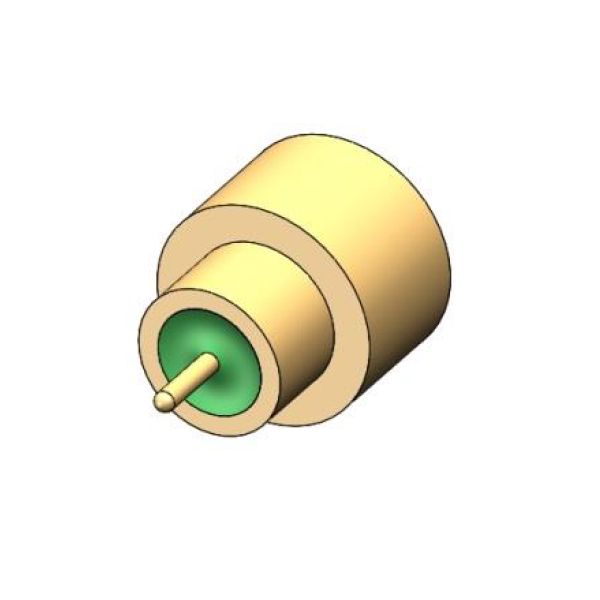
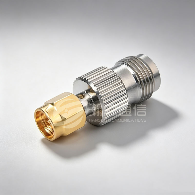
 SMP-J Hermetically Sealed RF ConnectorGlass-to-metal sealed SMP-J connector for panel or tube-shell mounting, suited to blind-mate RF joints where sealing and repeated mating cycles both matter.View Product →
Failure Modes and What They Usually Mean
A failed seal test is a symptom, not a diagnosis. The table below maps the common signatures to the first place worth looking.
| Signature | Likely cause | First check |
|---|---|---|
| Fine leak fails, gross leak passes | Pinhole in the lid weld, void at the glass-to-metal interface, plating porosity | Seal cross-section and plating thickness |
| Gross leak fails outright | Cracked glass bead, incomplete solder fillet, handling damage | Reflow profile and inspection records |
| Passes at build, fails after temperature cycling | Expansion mismatch stressing the glass bead or the joint | Material pairing and bead geometry |
| Readings differ between laboratories | Ambient helium background, transfer delay, different condition letter | Calibrated leak check and method comparison |
Frequently Asked Questions
What is the difference between a fine leak test and a gross leak test?
The fine leak test uses helium to find leaks between roughly 10⁻⁹ and 10⁻⁵ atm·cc/s. The gross leak test catches anything larger, using bubble emission or penetrant weight gain. A part needs both, because each is blind to the other's range.
What leak rate does MIL-STD-883 Method 1014 actually require?
There is no single figure. The reject limit is derived from the internal cavity volume of the package and is confirmed by the device drawing. Ask for the limit and the condition letter together, never the limit alone.
Why did my part pass the seal test and still leak in the field?
A helium test is a snapshot of one moment. Reflow, mating force, vibration and thermal cycling can open a seal that was sound at test. Background helium or a long transfer delay can also hide a real leak during the test itself.
How long does a helium leak test take?
Budget days rather than minutes. The cycle includes a dry bake, a pressurised helium soak, a controlled wait and the mass spectrometer read. Flexible conditions for larger cavities extend the soak further.
Does Method 1014 apply to RF connectors and cable assemblies?
The method is written for microelectronic devices and packages. Connector detail specifications often call their own seal test, so the governing document should be stated explicitly. A sealed connectorised module is commonly qualified to Method 1014.
What causes a gross leak failure most often?
An incomplete solder or weld fillet, a cracked glass bead, or damage picked up in handling and de-panelling. Gross leak failures are rarely subtle and usually visible under magnification once you know where to look.
Looking For Business Opportunity?
Request for a call today
-

+86-15715730755
-

-

No. 1, Longcao Road, Dongqian Lake Tourism Resort Industrial Zone, Yinzhou District, Ningbo City, Zhejiang, China.
Message
Copyright © Ningbo Hanson Communication Technology Co., Ltd.
