


 English
 русский
Industry News
 Home / News / Industry News / RF Cable Types: A Practical Guide to Coax Styles, Signal Loss and Selection
RF Cable Types: A Practical Guide to Coax Styles, Signal Loss and Selection
 2026.11.04
 Industry News
A 1 m RG58 jumper costs you about 1 dB at 2.4 GHz, which is roughly 20% of the power going in. Swap it for a 0.141 in semi-rigid cable and the same run loses a little over half that. Nothing else in the assembly changed — only the cable type did.
That is why the cable family is usually the first decision worth getting right when comparing RF cable types. Impedance decides what the cable is allowed to connect to, construction decides how much signal reaches the far end, and the connector interface caps the frequency the finished assembly can carry. What follows covers how the families differ, what datasheet numbers actually mean, and where orders most often go wrong.
Content
- 1 The main RF cable types, compared
- 2 Impedance comes first: 50 or 75 ohm
- 3 Inside the cable: four layers, four jobs
- 4 Reading loss figures without getting fooled
- 5 Connector interfaces set the ceiling
- 6 Matching cable to connector and to the job
- 7 Five details that cause rework
- 8 Frequently asked questions
The main RF cable types, compared
Nearly every catalogue cable falls into one of five families. They overlap in impedance and connector options, so the real differences come down to loss for a given diameter, how tight you can bend them, and whether the run will ever be re-routed.
| Family | Typical sizes | Loss at 1 GHz (dB/m) | Best suited to | Main trade-off |
|---|---|---|---|---|
| Flexible (RG-style) | RG316, RG58, RG213, 1.9–10.3 mm | 0.3–1.2 | Bench jumpers, short runs, lab patching | Highest loss for a given diameter |
| Low-loss flexible | 0.240 in, 0.400 in, foam or air-spaced | 0.1–0.45 | Antenna feeders, in-building runs | Stiffer jacket, wider bend radius |
| Semi-rigid | .047–.250 in, solid PTFE, copper tube | 0.2–1.2 | Phase-critical paths, dense internal routing | Cannot be re-routed after forming |
| Conformable | .086–.250 in, hand-formable | 0.25–1.0 | Tight enclosures, prototype routing | Less repeatable, shorter flex life |
| Corrugated (hardline) | 1/2 in, 7/8 in | 0.05–0.15 | Long feeders, high power, outdoor runs | Bend radius and connector cost |
Over a 10 m run at 2 GHz, RG58 loses roughly 9 dB where 0.240 in low-loss cable loses about 3 dB. That gap comes from the dielectric and the shield, not from the copper.
Impedance comes first: 50 or 75 ohm
Two impedances cover almost all RF work, and they are not interchangeable.
50 ohm
- Wireless, radar, GPS, test instruments
- Standard for SMA, N, TNC and 2.4 mm interfaces
- Default for anything carrying a modulated signal
75 ohm
- Broadcast video, CATV, satellite IF distribution
- Common in BNC and F connectors
- N-type is rarely produced in 75 ohm
A 75-ohm plug on a 50-ohm jack does not fail outright — it reflects. The joint adds return loss, the source sees a worse load, and a sweep shows ripple that often gets blamed on the cable. Mixing is easiest to get wrong with BNC, where the 50 and 75 ohm versions look identical from the outside and differ only in the dielectric and centre pin.
Inside the cable: four layers, four jobs
Each layer moves a different number on the datasheet, which is why two cables with the same impedance can behave very differently.
- Centre conductor: solid copper for lowest loss and stable phase; stranded for flex life.
- Dielectric: solid PE (velocity factor about 0.66) is cheap and stable, foamed PE (0.80–0.88) cuts loss but is softer, solid PTFE (about 0.70) handles heat and suits semi-rigid builds.
- Shield: a single braid gives 90–95% coverage, while foil plus braid approaches full coverage and improves screening at high frequency — at the cost of stiffness.
- Jacket: PVC indoors, FEP for temperature and chemical resistance, TPU for outdoor abrasion.
Velocity factor is the item buyers most often skip. A solid-PE cable with a factor of 0.66 is electrically 1.5 times its physical length, so 3 m of coax behaves like 4.5 m of free space. That matters for phase-matched pairs, delay lines and antenna harnesses, where two cables of equal physical length can still arrive out of step if their dielectrics differ.
Reading loss figures without getting fooled
Datasheet attenuation is measured on a swept analyser at room temperature into matched 50-ohm loads, and quoted either in dB per 100 ft or dB per 100 m. Unit conversion is where mistakes creep in: 0.5 dB/100 ft is the same cable as 1.6 dB/100 m, yet the two numbers look far apart on a quotation sheet.
Loss climbs roughly with the square root of frequency, so a cable quoted at 1 GHz is about 2.4 times lossier at 6 GHz. If the link runs at 3.5 GHz, ask for attenuation at 3.5 GHz rather than the headline number, and confirm the tolerance — plus or minus 5% between production lots is normal.
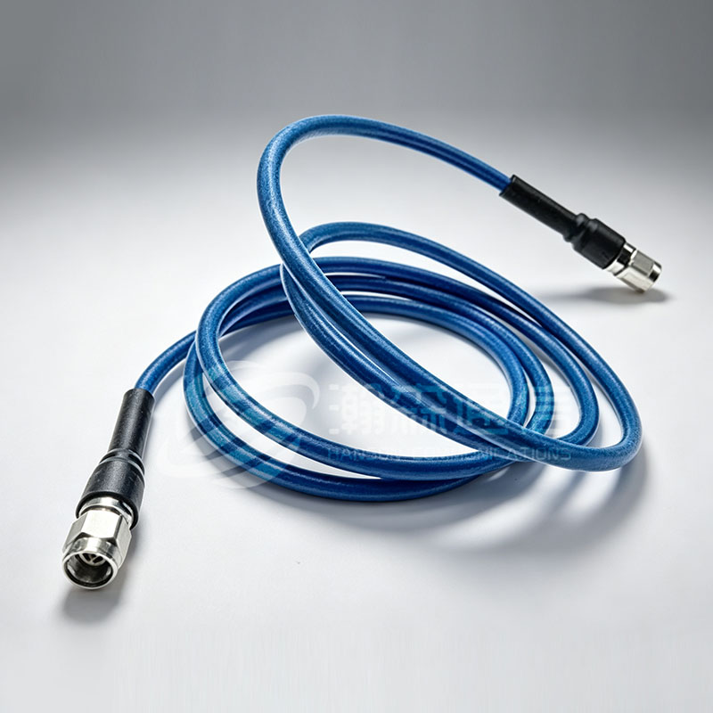 Super Low-Loss Flexible RF Cable AssemblyPre-terminated assembly for high-frequency links, offering ultra-low insertion loss and stable phase performance where every decibel matters.View Product →
When every tenth of a decibel counts, a pre-terminated super low-loss flexible assembly removes both the crimp and the guesswork from that calculation.
Connector interfaces set the ceiling
The interface caps the assembly. An SMA-terminated cable will not deliver 40 GHz simply because the coax is rated higher — the connector's upper limit governs, and so does the launch into the board or module it mates with.
| Interface | Typical maximum | Common cable pairing | Notes |
|---|---|---|---|
| BNC | 4 GHz | RG58, RG174 | Bayonet coupling, quick lab patching |
| TNC | 11 GHz | RG58, RG316 | Threaded BNC variant, better under vibration |
| N-type | 11–18 GHz | 0.400 in, 1/2 in corrugated | Outdoor feeders, medium power |
| SMA | 26.5 GHz | .141 in semi-rigid, RG316 | Most common microwave interface |
| 2.4 mm | 50 GHz | .086 in, .141 in | Precision test, instrument ports |
| 1.85 mm | 67 GHz | .047–.086 in | High-frequency instruments and modules |
Choose the interface first, then the cable that fits it. Each connector body is machined for a defined range of cable diameters, so a connector built for RG58 will not seat on 0.240 in low-loss cable even though both are 50 ohm.
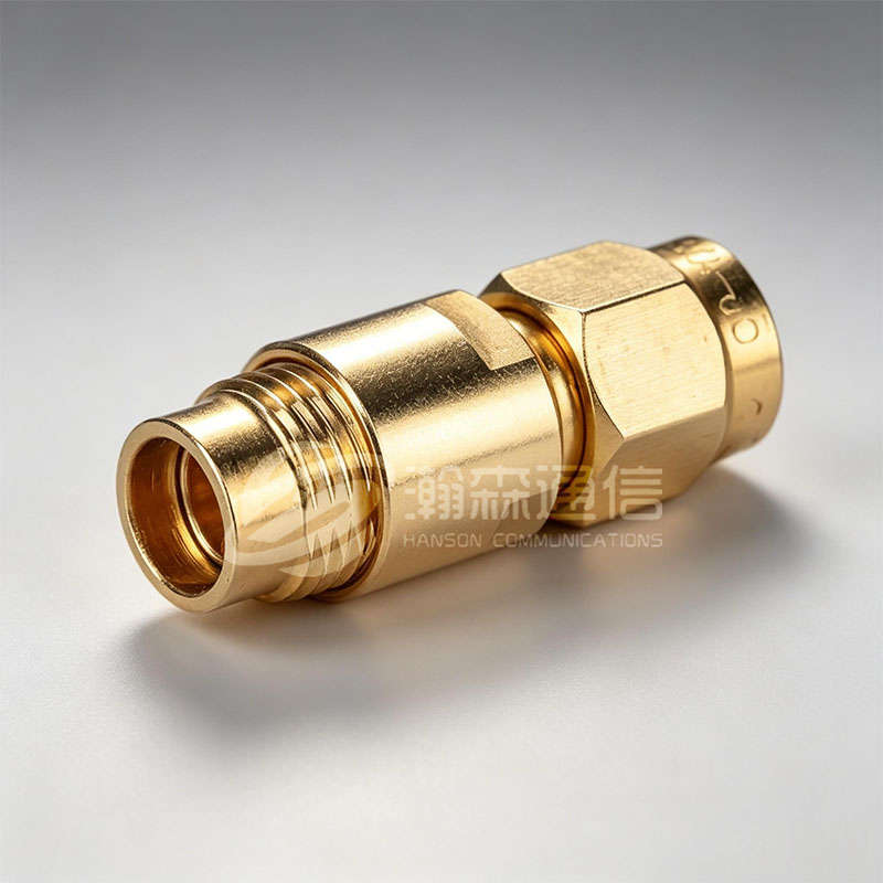
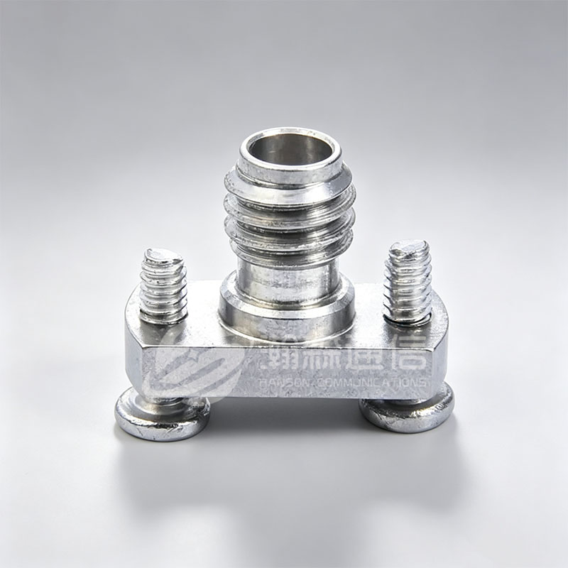
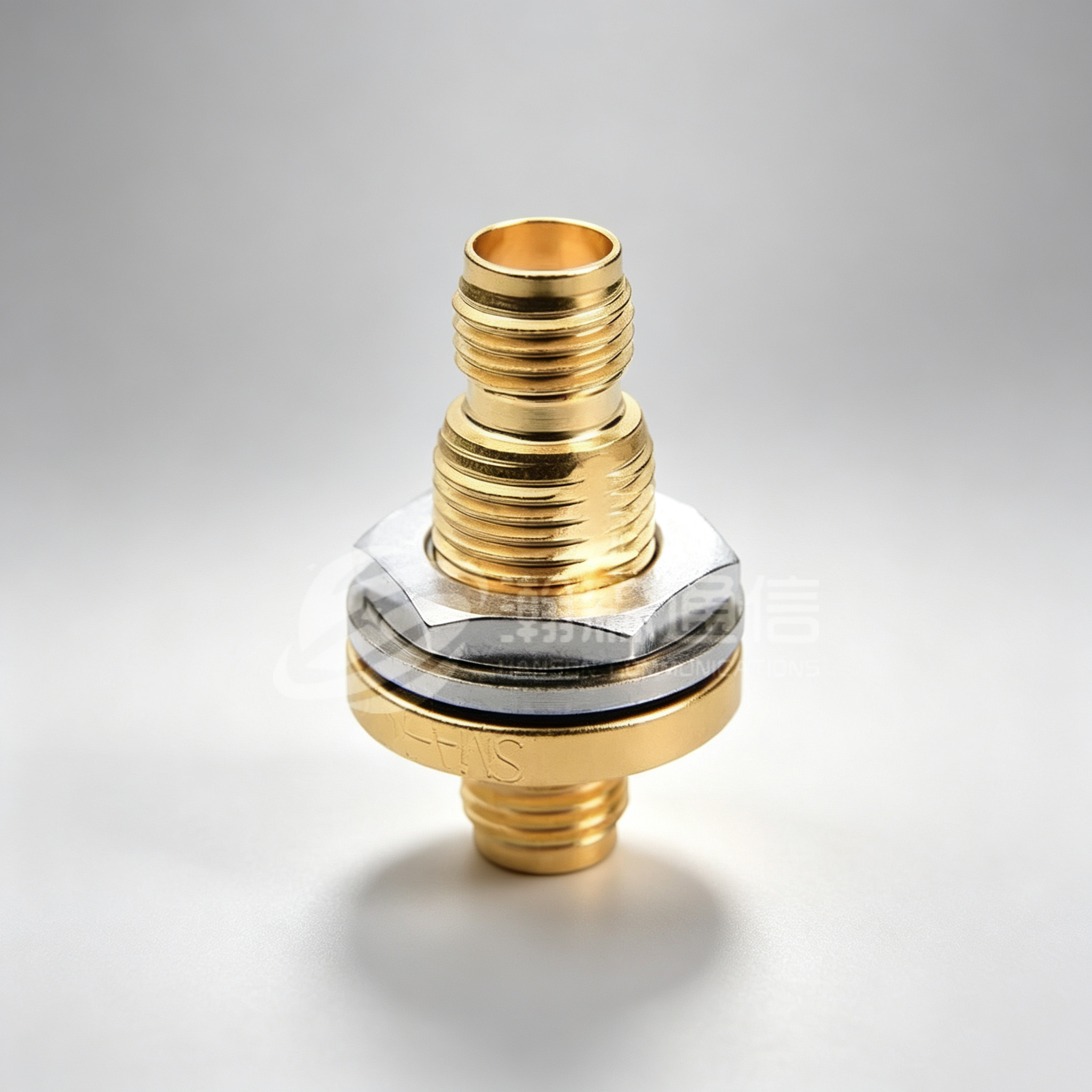
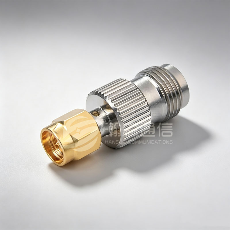
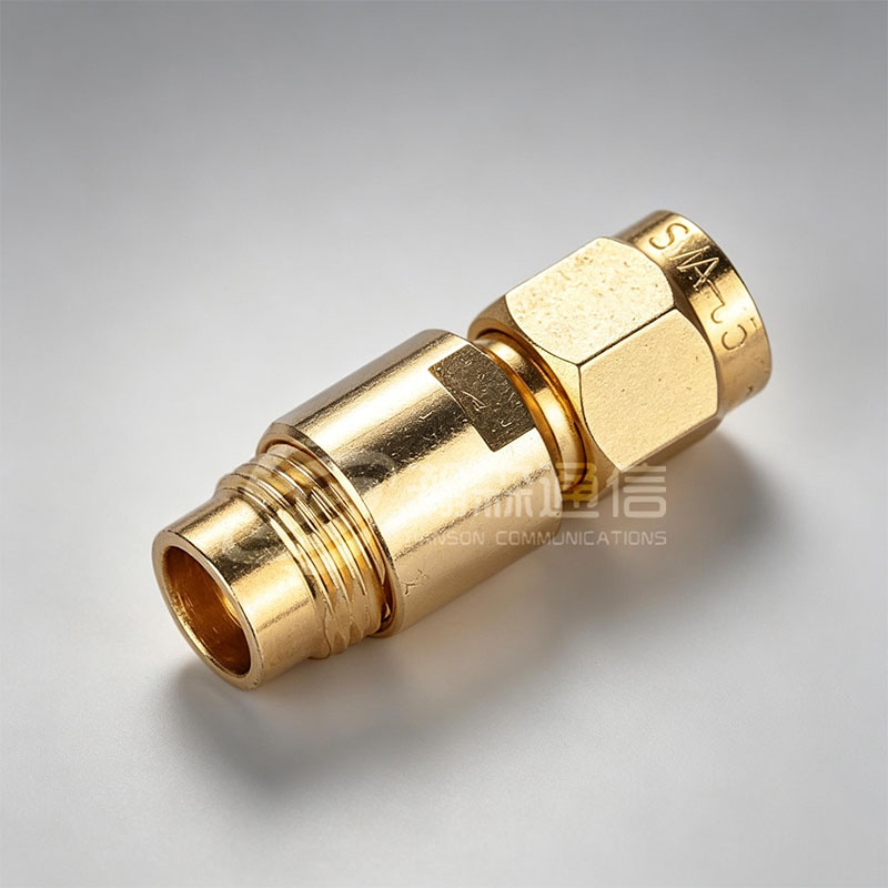 SMA RF Coaxial Connector SeriesThreaded 50Ω connectors covering DC–26.5 GHz, with male and female variants and cable compatibility tables for matching interfaces to assemblies.View Product →
SMA remains the workhorse of bench and microwave work, which is why it appears in so many of the assemblies we build.
Matching cable to connector and to the job
Most selection arguments disappear once the application is named. These pairings cover the majority of orders:
- Bench and lab, under 1 m: RG316 or RG58 with SMA. A few tenths of a decibel hardly matter next to flexibility and cost.
- Outdoor feeder, 10–50 m: 0.400 in low-loss or 1/2 in corrugated with N-type. Weatherproofing the joint matters more than the last 0.3 dB.
- Phase-critical harness: semi-rigid, or flexible cable supplied as a phase-matched set with a stated tolerance in degrees at a stated frequency.
- Low-PIM sites: assemblies specified by PIM value under a two-tone test, usually around -150 dBc, rather than by insertion loss alone.
- Bulkhead, vacuum or pressure boundary: hermetically sealed connectors and glass-to-metal seals where the joint has to hold pressure as well as signal.
If crimping in-house is not practical, pre-terminated assemblies arrive tested and labelled; this overview of what RF cable assemblies do covers the extra checks that come with them.
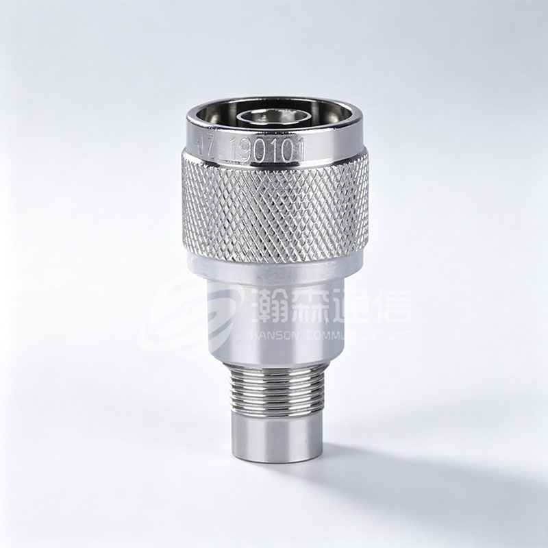
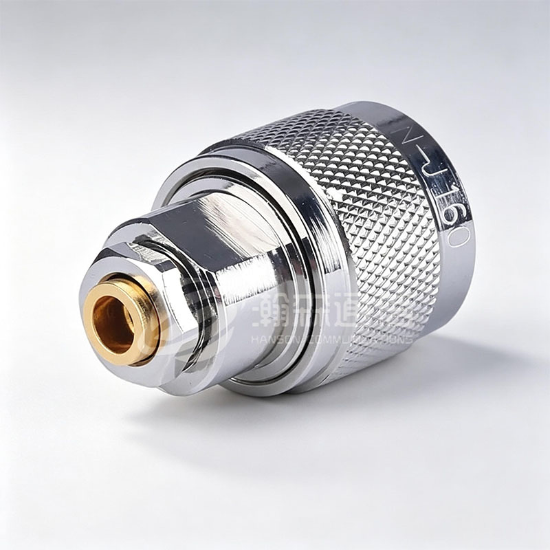 N-Type RF Coaxial Connector SeriesThreaded 50Ω and 75Ω connectors rated to DC–18 GHz and DC–3 GHz, suited to feeder runs that face weather, torque and repeated mating.View Product →
For feeder runs, the N-type body is usually the deciding part of the bill of materials, since it must survive weather, torque and repeated mating.
Five details that cause rework
- Mixing dB/100 ft and dB/100 m on the same comparison sheet. Convert everything first, then compare.
- Quoting a matched pair by length alone. Velocity factor has to match too, or the pair is only matched at one frequency.
- Ordering a connector without checking its cable group. The datasheet lists the cable types the body was machined for.
- Ignoring bend radius. A kink changes impedance permanently; flexible cables are commonly quoted at ten times the outer diameter.
- Leaving temperature and ingress unstated. A PVC jacket is fine indoors and a poor choice on a mast, while FEP or TPU usually costs very little more.
Frequently asked questions
What are the different types of coaxial cable?
The main RF cable types are flexible RG-style, low-loss flexible, semi-rigid, conformable and corrugated hardline, each split again by impedance and diameter.
Is 50 ohm better than 75 ohm?
Neither is better. 50 ohm suits wireless, radar and test gear; 75 ohm suits video and CATV distribution. Mixing the two causes reflections at the joint.
What is the difference between RG58 and RG316?
Both are 50-ohm flexible cables, but RG316 is about 2.5 mm in diameter with a PTFE dielectric, while RG58 is roughly 5 mm with solid PE. RG316 bends tighter and loses more per metre.
Which RF cable type has the lowest loss?
Large corrugated hardline is lowest, typically well under 0.15 dB/m at 1 GHz. Among small cables, 0.400 in low-loss flexible is usually the practical choice.
Can I use an SMA connector on RG58 cable?
Only with a connector body machined for that cable group. SMA is made in several sizes for different diameters, and the wrong one will not crimp correctly or hold impedance.
What is a low-PIM cable assembly used for?
Low-PIM assemblies are used where weak signals share a site with strong transmitters, such as cellular installations. They keep passive intermodulation below a specified limit, usually around -150 dBc.
Looking For Business Opportunity?
Request for a call today
-

+86-15715730755
-

-

No. 1, Longcao Road, Dongqian Lake Tourism Resort Industrial Zone, Yinzhou District, Ningbo City, Zhejiang, China.
Message
Copyright © Ningbo Hanson Communication Technology Co., Ltd.
