


 English
 русский
Industry News
 Home / News / Industry News / High Power RF Connectors: Selection, Thermal Limits, and Installation Guide
High Power RF Connectors: Selection, Thermal Limits, and Installation Guide
 2026.10.28
 Industry News
At 1 kW continuous, a high-power RF connector is a thermal and mechanical component, not a passive accessory. The first decision is not which shell looks strongest; it is what average power, peak power, frequency, VSWR, ambient temperature, and cable interface the system will actually present. A connector rated for 500 W at 25°C may be limited to less than half that inside a sealed outdoor enclosure at 70°C. Start with the derated power budget, then choose the interface.
Content
Start With a Derated Power Budget
The useful rating is the average power the connector can pass at the worst-case ambient temperature, not the headline number on a short-form datasheet. Average power heats the center contact, dielectric, and outer conductor. Peak power stresses the air gap and dielectric before breakdown, especially at altitude or with a high VSWR. A 2.0:1 VSWR reflects 11.1% of forward power, calculated as ((VSWR - 1)/(VSWR + 1))^2; at 1 kW, that is 111 W returning through the same surfaces.
Check four derating inputs before comparing families: ambient temperature inside the enclosure, altitude, continuous versus pulsed duty, and cable/connector interface size. For pulsed systems, use pulse width and duty cycle to calculate average power, then verify peak voltage against the interface breakdown margin. A connector that is comfortable at 100 W average can fail at 1 kW peak if the dielectric and air gap are not sized for it.
For 50-ohm medium-power systems, an N-type interface is a common starting point, but the datasheet derating curve still decides.
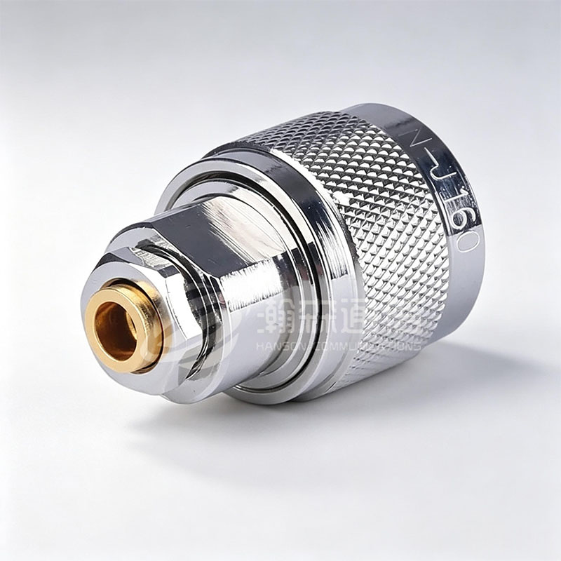 N-Type RF Coaxial Connector Series50Ω and 75Ω threaded N-type connectors for medium-power RF systems; 50Ω types cover DC–18 GHz and support many cable interfaces.View Product →
The Connector Families That Carry High Power
Power handling is set by geometry, materials, and thermal path. Interface dimensions and test methods are standardized under IEC 61169 and MIL-STD-348, but power ratings remain manufacturer-specific. The table below is a shortlisting aid, not a substitute for the rating at your frequency and ambient.
| Family | Coupling | Typical frequency | High-power role | Main watch-out |
|---|---|---|---|---|
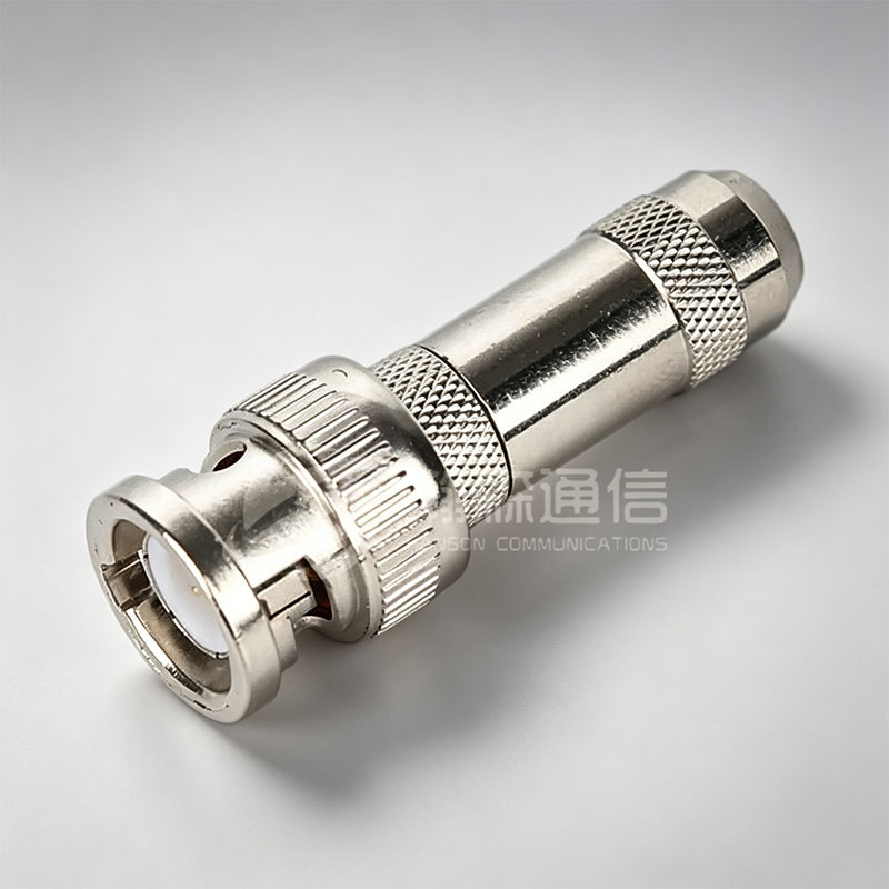
| N-type | Threaded | DC to 11 GHz, some to 18 GHz | Medium-power 50-ohm systems | Center contact and cable joint dominate heating |
| 7-16 DIN | Threaded | DC to 7.5 GHz | High average power and low PIM | Larger size, heavier panel load, torque control |
| C-type | Bayonet | DC to 11 GHz | High power with quick mating | Contact wear and alignment after repeated mating |
| EIA flanged | Bolt or flange | HF/VHF and broadcast bands | Very high power rigid line | Mechanical support, corona, and seal integrity |
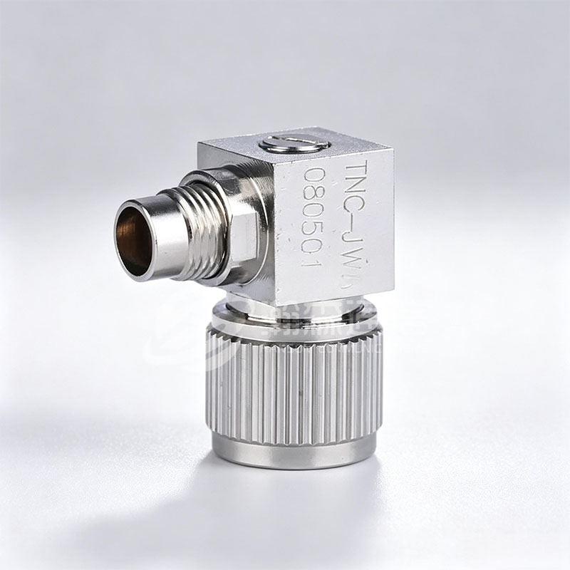
| TNC | Threaded | DC to 11 GHz | Medium power in compact packages | Lower thermal mass than N-type or 7-16 DIN |
| SMA | Threaded | DC to 18 GHz, precision variants higher | Low to medium power | Small center contact limits thermal headroom |
The 7-16 DIN is often selected when average power and passive intermodulation matter more than size. N-type remains popular because it fits many 50-ohm systems and cable sizes. Do not assume a smaller precision interface can carry the same power as a larger one simply because both use silver-plated contacts; the center-contact mass and dielectric volume are different.
Thermal Rise, VSWR, and the Derating Trap
VSWR is not just a return-loss number. Reflected power adds loss and can raise connector temperature. The chart shows the calculated reflected-power fraction for common VSWR values; it is physics, not a product curve.
Calculated from the standard VSWR reflection formula: ((VSWR - 1)/(VSWR + 1))^2.
At 3.0:1 VSWR, one-quarter of forward power is reflected. That reflected wave can double voltage stress at some points and increase heating in the connector and cable. If the system must survive a worst-case mismatch, size the connector for the reflected power and voltage margin, not just the matched-load rating.
Cable interface and assembly quality also change the thermal result. A low-loss cable assembly with a well-controlled solder or compression joint spreads heat away from the center contact; a poor joint concentrates it.
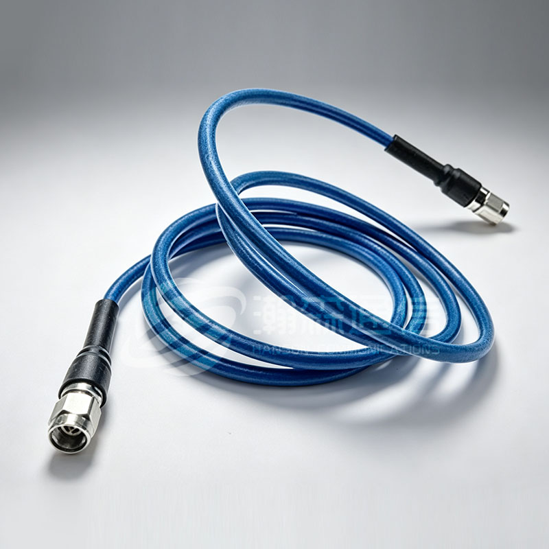 Super Low-Loss Flexible RF Cable AssemblyFlexible 50Ω assembly for high-frequency signal integrity, offering low insertion loss, stable phase, and SMA, N-type, or TNC connector options.View Product →
Interface Geometry and Contact Metallurgy
A high-power connector has three heat paths: the center contact, the dielectric, and the outer conductor. The center contact carries current and must conduct heat to the mating pin and cable conductor. The dielectric must hold voltage stress without excessive loss. The outer conductor carries return current and provides the mechanical reference.
Plating lowers contact resistance, but thickness, substrate, and mating surface finish matter. Silver plating is common for low loss and high conductivity; gold is common for corrosion resistance and many mating cycles. A thin or porous plating can raise contact resistance, create hot spots, and increase PIM. Inspect mating surfaces for scratches, burnishing, and dielectric chips before assembly.
Adapters add two mating interfaces. Each interface adds contact resistance, a possible reflection, and a thermal joint. For test benches and short extensions, use a quality adapter rated for the same frequency and power class; do not treat it as a lossless mechanical part.
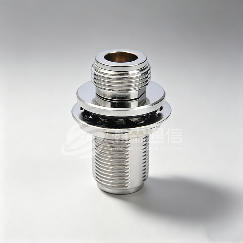 N-Type to N-Type RF Coaxial AdapterDC–18 GHz N-type adapter with 1.15 VSWR and 2500 Vrms withstand voltage; suitable for test benches and short RF extensions.View Product →
Installation Details That Decide Whether 1 kW Stays 1 kW
Most high-power connector failures start at assembly, not in the design. The center pin must be centered, the dielectric must be clean, the cable prep must match the connector drawing, and torque must be applied to the correct surfaces. A loose coupling nut raises contact resistance; an over-torqued nut can deform the interface and damage the dielectric.
Use a calibrated torque wrench, follow the manufacturer mating sequence, and support the cable so the connector does not carry bending load. For outdoor enclosures, seal the cable entry, not the connector mating plane, unless the connector is designed for that sealing method. After mating, check that the coupling is fully engaged and that the panel gasket is compressed evenly.
- Center contact depth within the gauge limit.
- No dielectric chips, metal burrs, or plating scratches.
- Coupling torque set to the datasheet value.
- Cable strain relief independent of the connector body.
- VSWR sweep at the operating band before full power.
For a step-by-step mating and torque sequence, see this RF coaxial connector installation guide.
Testing and Verification Before You Commit
A high-power connector should be verified at the system level, not only as a component. Run a VSWR and insertion-loss sweep across the operating band, inspect the assembled joint with thermal imaging under load, and repeat the measurement after a thermal cycle. For sealed or outdoor units, add insulation-resistance and leak tests if the design requires them.
- Measure VSWR and insertion loss at the operating frequency and at the band edges.
- Apply rated average power with a matched load, then repeat with the worst-case VSWR.
- Use thermal imaging to find hot spots at the center contact, cable joint, and adapter interfaces.
- Perform a mating-cycle check and inspect plating and dielectric after the test.
- Record torque, ambient temperature, and test duration so the result is traceable.
If the connector passes only at 25°C and low VSWR, it is not yet a high-power design. The acceptance criterion should match the enclosure temperature, altitude, and mismatch the field will see.
Frequently Asked Questions
What is a high power RF connector?
A connector designed to carry high average or peak RF power with acceptable thermal rise, voltage stress, and contact resistance, usually with a larger center contact and dielectric than low-power types.
Can an N-type connector handle 1 kW?
It depends on frequency, ambient temperature, VSWR, cable interface, and duty cycle. Check the derating curve; a 1 kW matched-load rating may fall sharply at 70°C or high VSWR.
What is the difference between average power and peak power?
Average power heats the connector over time; peak power stresses the dielectric and air gap. Pulsed systems need both checks.
Why do high power RF connectors heat up?
Contact resistance, dielectric loss, reflected power, and poor cable joints convert RF energy into heat. A hot center contact is a common warning sign.
Is 7-16 DIN better than N-type for high power?
7-16 DIN usually offers more thermal mass and lower PIM for high average power, but N-type is smaller and adequate for many medium-power systems. Compare derated ratings, not just size.
How often should high power RF connectors be inspected?
Inspect at commissioning, after any mismatch event, and on a scheduled maintenance interval based on mating cycles, outdoor exposure, and thermal cycling.
Looking For Business Opportunity?
Request for a call today
-

+86-15715730755
-

-

No. 1, Longcao Road, Dongqian Lake Tourism Resort Industrial Zone, Yinzhou District, Ningbo City, Zhejiang, China.
Message
Copyright © Ningbo Hanson Communication Technology Co., Ltd.
