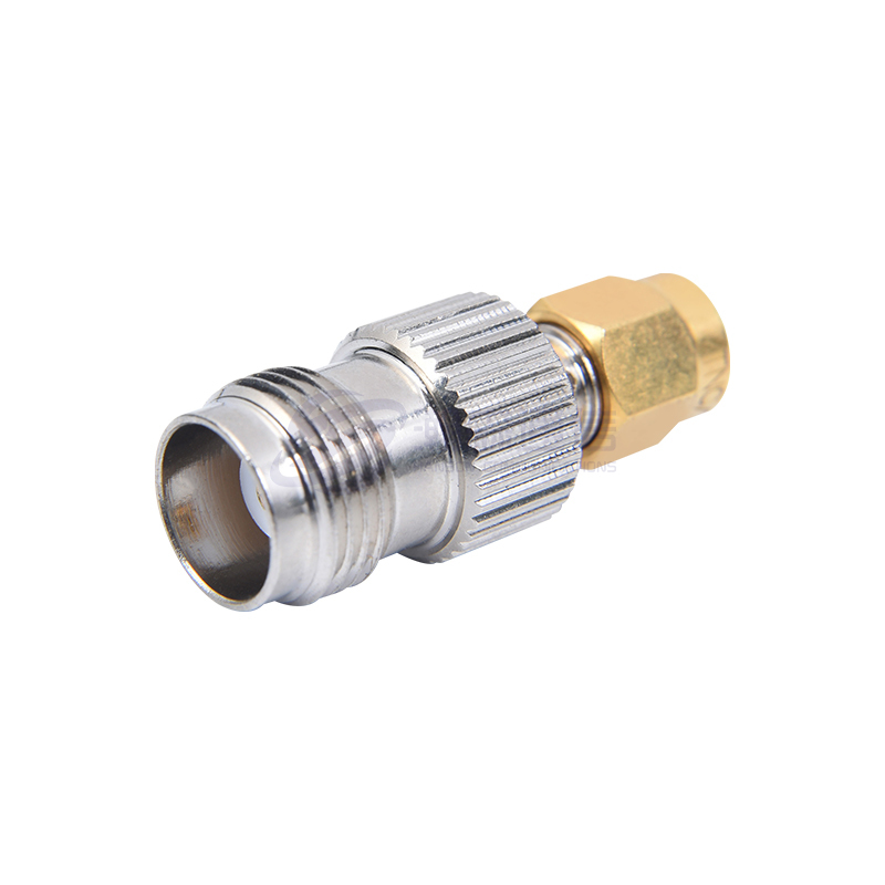
What is an RF coaxial adapter?
 2025.09.11
 Industry News
1.RF Coaxial Adapter: Definition and Working Principle
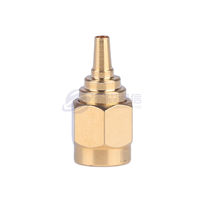
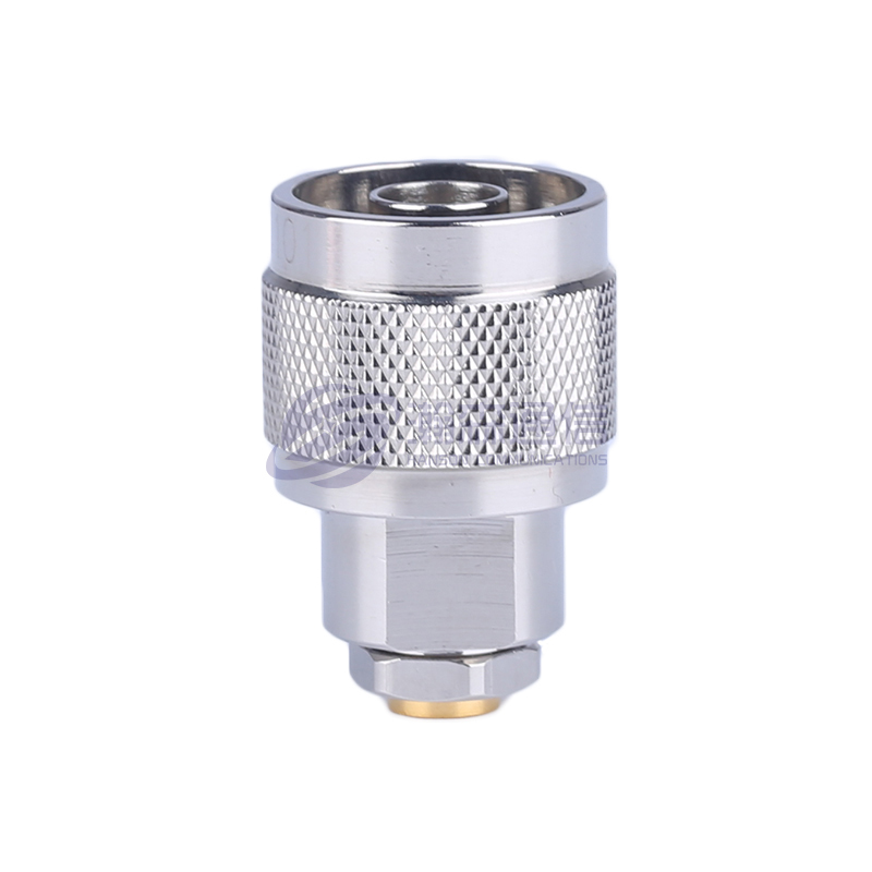
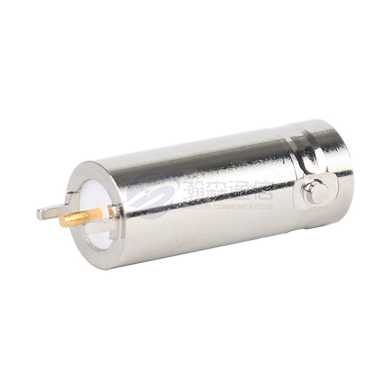
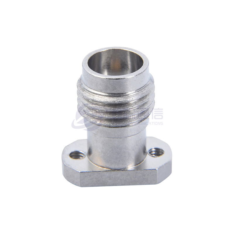
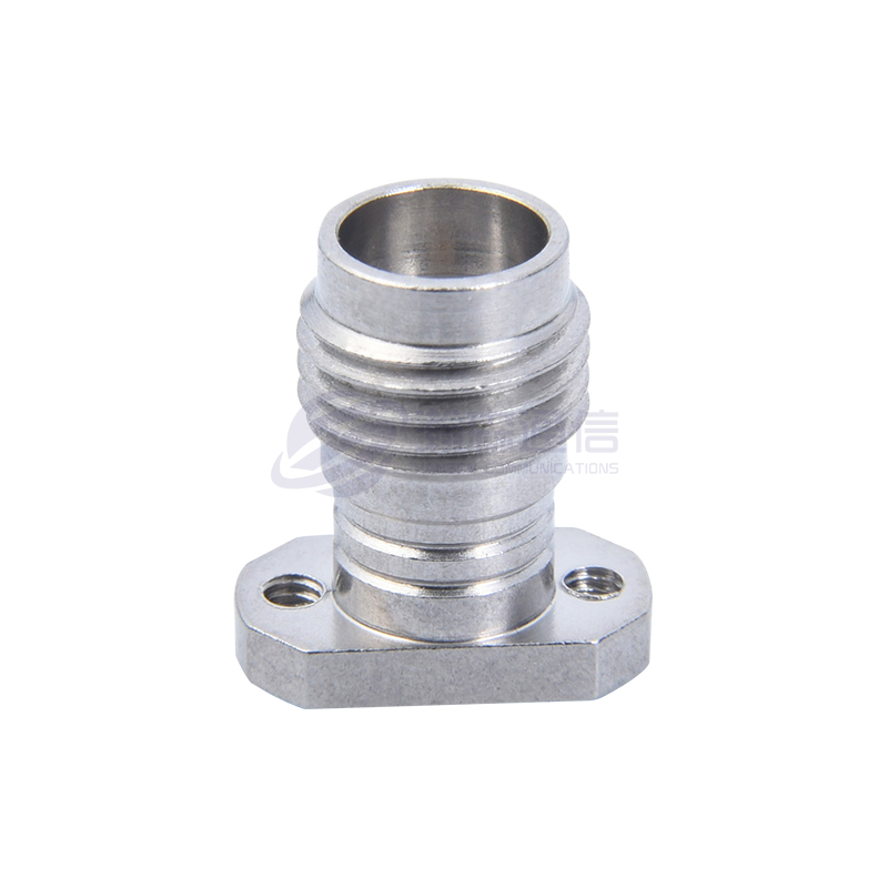
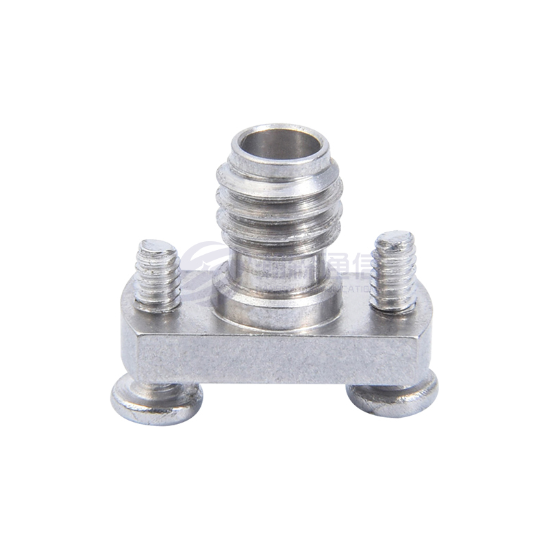
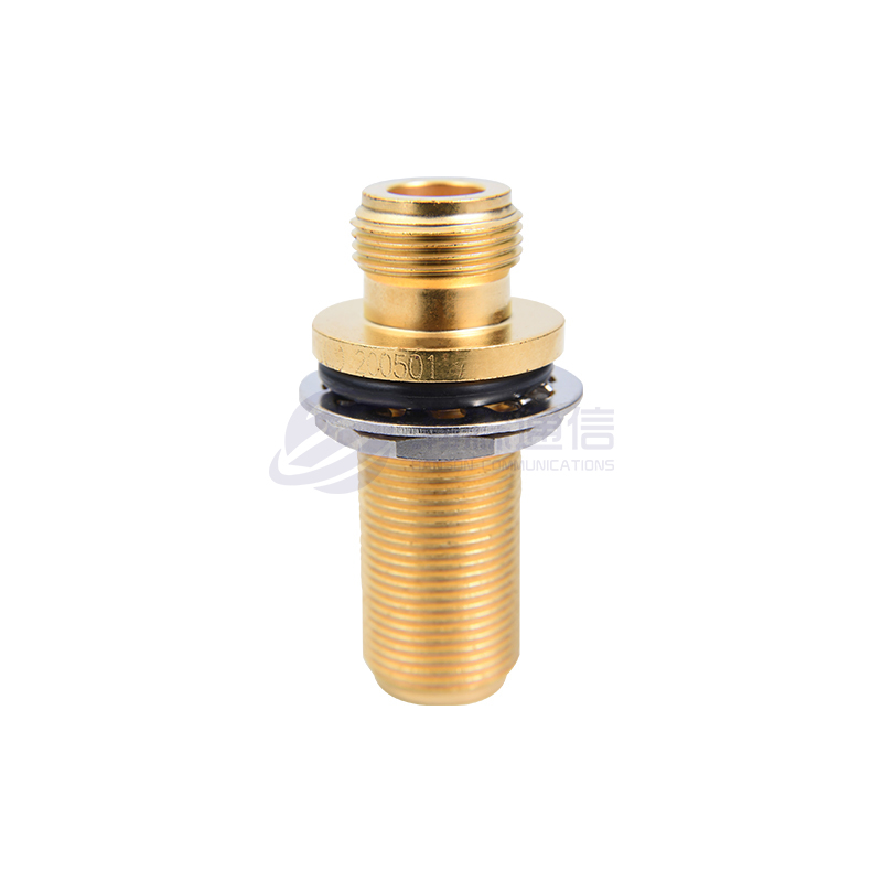
RF coaxial adapters are key components in RF engineering, primarily used to connect coaxial cables and connectors of different interface types or sizes, ensuring low loss, high stability, and impedance matching during signal transmission. They play a vital role in wireless communications, test and measurement, aerospace, and consumer electronics, resolving interface incompatibilities between devices while ensuring high-frequency signal integrity. RF coaxial adapters primarily serve to change connection methods, convert interface types, or adapt to devices with different frequency and impedance requirements.
The core structure of an RF coaxial adapter consists of an outer conductor (a metal shell, typically made of gold-plated brass or aluminum alloy), an inner conductor (a center conductive pin, often made of gold-plated copper or beryllium copper), an insulating medium (such as PTFE), and a specific connector structure (such as SMA, N-type, or BNC). The outer conductor provides electromagnetic shielding and mechanical protection, while the inner conductor transmits the signal, and the insulating medium isolates the inner and outer conductors and maintains impedance matching.
In RF signal transmission, the operating principles of the adapter are primarily based on continuous impedance matching, electromagnetic field confinement, and mode suppression. Impedance matching is achieved through the carefully designed ratio of the inner and outer conductor diameters and the dielectric constant of the dielectric material, ensuring that signal transmission avoids reflections caused by impedance changes (typically measured by the voltage standing wave ratio (VSWR), with an ideal value of 1:1). Electromagnetic field confinement relies on the shielding effect of the outer conductor, confining electromagnetic waves to the inner conductor, preventing signal leakage and external interference. Furthermore, optimized structural design suppresses higher-order modes (such as TE/TM modes), ensuring stable transmission of the main TEM mode, thereby reducing signal distortion.
The performance of RF coaxial adapters is determined by several key parameters, including frequency range (e.g., DC-18 GHz), impedance (typically 50Ω or 75Ω), voltage standing wave ratio (VSWR), insertion loss (energy attenuation during signal transmission), and power handling (maximum power handling). For example, in 5G communication systems, adapters must support high frequency bands (such as 3.5 GHz or millimeter wave (28 GHz)) while maintaining low insertion loss to prevent signal attenuation that affects communication quality. In high-power applications (such as radar or broadcast systems), power handling and heat dissipation performance become important selection considerations.
In practical applications, adapter selection requires comprehensive consideration of the interface type, operating frequency, power requirements, and environmental conditions. Common adapter types include SMA to N-type and BNC to SMA. Different interfaces have varying mechanical structures and electrical characteristics, so ensuring a perfect match between the adapter and the connector is crucial. Furthermore, long-term use can cause oxidation or mechanical wear on the contact surface, increasing contact resistance and impacting signal transmission. To address these issues, high-precision machining (such as controlling the inner conductor concentricity to within 0.05mm) and surface gold plating are widely used to reduce contact resistance and improve durability.
Typical Application Scenarios
Test and Measurement: Connecting test equipment with different interfaces (such as vector network analyzers)
Communication Systems: Adapters between base station antennas and RF modules
Military and Aerospace: Adapters for different-shaped interfaces in radar and satellite communication systems
Consumer Electronics: R&D and debugging of 5G devices and Wi-Fi modules
Structural Components
An RF coaxial adapter consists of the following core components:
Outer Conductor (Shell): Typically made of metal (such as gold-plated brass), providing shielding and mechanical protection
Inner Conductor: The center conductive pin responsible for signal transmission, typically made of gold-plated copper or beryllium copper
Insulation: Materials such as PTFE (polytetrafluoroethylene) that isolate the inner and outer conductors and maintain impedance matching
Interface: Threaded, snap-fit, or other connection methods (such as SMA, N-type, BNC, etc.)
2. The Function of an RF Coaxial Adapter
RF coaxial adapters play a crucial role in RF systems. Their core functions can be summarized as follows:
Interface Conversion Bridge
The primary function of an RF coaxial adapter is to convert between different RF connector types and specifications. In practical applications, mismatches between device ports and cable interfaces are common, such as when a test instrument uses an N-type connector and the device under test has an SMA connector. The adapter's sophisticated mechanical design allows for seamless connection between different connector types, such as SMA female and N-type male, eliminating system setup issues caused by interface incompatibility.
Signal Transmission Guarantee
High-quality RF coaxial adapters ensure impedance continuity during signal transmission through strict impedance control (typically 50Ω or 75Ω). Their high-precision internal concentric structure, combined with low-loss dielectric materials (such as PTFE), keeps signal reflection ratio (VSWR) below 1.5:1, effectively reducing the impact of standing waves on system performance. In frequency bands below 6 GHz, high-quality adapters can achieve insertion loss below 0.3 dB.
System Expansion Hub
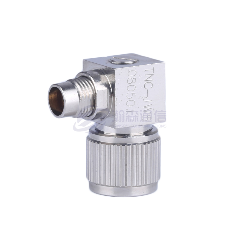
In complex RF systems, adapters enable multi-path signal distribution and routing. By combining different types of adapters, engineers can flexibly build test systems. For example, using a dual-female adapter to split a single signal into two, or using a right-angle adapter to redirect a signal to fit within a confined space. This flexibility is particularly important in space-constrained scenarios such as base station installations and in-vehicle RF systems.
Key Test and Measurement Components
In RF parameter testing, adapter quality directly impacts measurement accuracy. Devices like vector network analyzers rely on adapters to connect to the DUT (device under test). The adapter's impedance mismatch, loss, and other characteristics are factored into the measurement results. Therefore, metrology-grade adapters typically use air dielectric and gold plating to maintain excellent impedance matching characteristics (VSWR < 1.2:1) even in the 18 GHz band.
Adaptable to Special Environments
Adaptors are available in a variety of specialized models for different application scenarios:
High-voltage adapters feature reinforced insulation and can withstand voltages exceeding 10kV.
High-power adapters utilize silver plating and forced cooling, with a power capacity of up to 500W.
Triaxial adapters provide an additional shielding layer for sensitive measurement applications.
Explosion-proof adapters meet the requirements of hazardous locations such as petrochemicals.
System Maintenance Interface
Adapters provide an interface transition solution for equipment maintenance and upgrades. When interface standards for older equipment are updated, adapters enable compatibility between old and new equipment without replacing the entire system, significantly reducing retrofit costs. For example, during the upgrade from 4G to 5G base stations, N-to-7/16 adapters are widely used to maintain compatibility with existing feeder systems.
Optimized Signal Quality
High-performance adapters utilize specialized design features to improve signal integrity:
Stepped impedance transformation structure expands the operating frequency band
Dielectric constant gradient material reduces interface reflections
Built-in filtering suppresses interference in specific frequency bands
Electromagnetic sealing enhances EMC performance.
RF coaxial adapters are used in different fields as follows:
(1). Communications
Base station and antenna connection: used to match RF cables with different interfaces to ensure signal transmission quality.
Fiber optic and RF conversion: realize interface adaptation of optical signals and RF signals in hybrid communication systems.
Satellite communications: connect satellite ground station equipment and antennas to ensure low-loss transmission of high-frequency signals.
(2). Test and measurement
Network analyzer: adapt to test ports with different interfaces, such as N-type to SMA.
Spectrum analyzer: connect probes or antennas of different specifications to expand the test range.
Signal generator: match output ports with the device under test to reduce reflection loss.
(3). Aerospace and defense
Radar system: adapt to RF components of different frequency bands to ensure signal integrity.
Military communication equipment: realize fast interface conversion in field radios and electronic warfare systems.
Satellite and missile systems: used for high-frequency signal transmission and adapt to harsh environments.
(4). Medical equipment
MRI radio frequency coil: connects the coil to the imaging system to ensure high-frequency signal stability.
RF ablation equipment: adapts the treatment probe to the host to ensure energy transmission efficiency.
(5). Automotive electronics
Vehicle-mounted radar (millimeter wave radar): adapts to 77GHz/79GHz radar modules and test equipment.
Vehicle to everything (V2X): connects the antenna to the communication module to support 5G/C-V2X signal transmission.
(6). Broadcasting and television
RF transmitter: matches feeders and amplifiers with different interfaces.
Satellite TV reception: converts the interface between LNB and receiver (such as F type to N type).
(7). Industry and Internet of Things
RFID system: connects the reader and antenna to optimize radio frequency identification performance.
Wireless sensor network: adapts to communication modules with different frequency bands, such as LoRa and ZigBee.
(8). Scientific research and education
Laboratory radio frequency experiments: flexibly connect various test equipment, such as oscilloscopes and signal sources. Teaching Demonstration: Helps students understand the principles of RF interface matching and signal transmission.

3.Common Faults of RF Coaxial Adapters
RF coaxial adapters, as key connectors in RF signal transmission, are widely used in communications, test and measurement, aerospace, medical equipment, and other fields. Their performance directly impacts signal transmission quality and system stability. However, with long-term use or improper operation, adapters can develop various faults, leading to signal attenuation, reflections, and even system failure. The following details common RF coaxial adapter faults and their causes, along with corresponding preventative and maintenance recommendations.
RF coaxial adapter faults can generally be categorized as poor contact, mechanical damage, impedance mismatch, electrical performance degradation, seal failure, abnormal frequency response, and excessive temperature rise. These faults may occur independently or in conjunction with each other, collectively impacting adapter performance.
Poor contact is one of the most common faults in RF coaxial adapters. It manifests itself as intermittent signal transmission, increased insertion loss, or a high standing wave ratio (VSWR). Poor contact can be caused by a variety of factors, with interface oxidation being the most common. Adapter connectors are typically gold- or silver-plated to enhance conductivity and corrosion resistance. However, prolonged exposure to moisture, salt spray, or chemical contamination can cause the plating to wear or oxidize, increasing contact resistance. Furthermore, frequent plugging and unplugging or rough handling can deform the pins or sockets, preventing a secure connection. Threaded adapters (such as N-type and SMA) that are not tightened properly can also lead to unstable signal transmission. In extreme cases, poor contact can cause arcing, further damaging the adapter or connected device.
Mechanical damage is another common failure, manifesting as cracked housings, stripped threads, or deformed connectors. RF coaxial adapter housings are typically made of metal (such as brass or stainless steel) to provide good shielding and mechanical strength, but they can still be damaged by external impact, excessive torque, or prolonged mechanical stress. For example, applying excessive torque with a wrench during installation can strip the threads or deform the housing, affecting signal transmission. Furthermore, the adapter's center conductor is fragile and can bend or break if misaligned during plugging and unplugging, severely impacting electrical performance. Vibration or shock environments (such as automotive and aviation applications) increase the risk of mechanical damage, so high-reliability adapters and anti-loosening measures are essential.
Impedance mismatch is a particular concern in RF systems. If the adapter does not match the system impedance, it can cause signal reflections, increased standing wave ratio (SWR), and even damage the transmitter. Standard RF systems typically use 50Ω or 75Ω impedances. Mixing adapters with different impedances (such as using a 50Ω adapter in a 75Ω system) can introduce significant impedance discontinuities, causing signal reflections. Furthermore, dimensional deviations within the adapter's internal conductors or substandard dielectric materials can cause impedance deviations from the nominal value. For example, some low-cost adapters may use non-standard dielectric materials with unstable dielectric constants, resulting in impedance fluctuations during high-frequency signal transmission. In high-frequency applications such as millimeter waves, adapter manufacturing accuracy is particularly critical for impedance matching. Dimensional errors as small as microns can significantly degrade performance.
Electrical performance degradation is a progressive failure that can occur in RF coaxial adapters over time. It primarily manifests as increased insertion loss, noise interference, or uneven frequency response. Causes of electrical performance degradation include aging of the internal dielectric, contamination of the conductor surface, or poor solder joints. For example, polytetrafluoroethylene (PTFE), a common dielectric material for adapters, offers excellent high-frequency characteristics and temperature resistance. However, it can age under prolonged high-temperature conditions, causing changes in the dielectric constant and thus affecting signal transmission. Furthermore, dust, oil, or other contaminants entering the adapter can increase contact resistance or introduce additional parasitic capacitance/inductance, impacting high-frequency signals. Poor soldering (such as loose soldering between the internal conductor and the connector) can also cause signal intermittency or introduce nonlinear distortion.
Sealing failure primarily affects waterproof and dustproof adapters, manifesting as internal water ingress, salt spray corrosion, or degraded electrical performance. Adapters used in outdoor communications equipment, automotive radar, or marine electronic equipment typically require a certain level of protection (such as IP67). Aging, damage, or improper installation of the sealing ring (such as by not tightening the waterproof nut) can allow moisture or salt spray to intrude and corrode the internal conductor or dielectric material. In extreme temperature fluctuations, the sealing material can also lose its elasticity due to thermal expansion and contraction, further degrading sealing performance. Sealing failure not only affects electrical performance but can also cause short circuits or equipment damage. Therefore, regular inspection of the adapter's seal is essential in harsh environments.
Abnormal frequency response refers to the adapter experiencing significant signal attenuation or a shift in resonance within certain frequency bands. RF coaxial adapters are typically optimized for specific frequency bands, and use outside their rated frequency range can degrade performance. For example, a standard SMA adapter is typically rated for 18 GHz. However, structural limitations may introduce significant insertion loss or resonance when used in millimeter-wave bands (e.g., 40 GHz). Furthermore, internal deformation of the adapter (such as a bent center conductor or uneven dielectric material) can alter its distributed capacitance or inductance parameters, leading to abnormal frequency response. In broadband or ultra-broadband systems, the adapter's frequency flatness is particularly important, and high-performance models are essential to ensure signal integrity.
Excessive temperature rise is a common problem with adapters in high-power applications, manifesting as a warm or even hot housing. During RF signal transmission, the adapter's contact resistance and dielectric loss convert into heat. Inadequate heat dissipation or exceeding the rated power can lead to excessive temperature rise. For example, in broadcast transmitters or radar systems, adapters must withstand average power levels of hundreds of watts or even kilowatts. If contact is poor or the material has poor thermal conductivity (such as a low-quality metal casing), heat can accumulate and damage the internal structure. Prolonged high temperatures can also accelerate dielectric aging and seal failure, further reducing the adapter's lifespan.
To reduce RF coaxial adapter failures, the following preventative and maintenance measures can be taken: First, properly install the adapter and tighten the connector according to the manufacturer's recommended torque specifications, avoiding overtightening or undertightening. Second, regularly inspect the adapter's condition, clean the connector (using absolute alcohol), and check for signs of oxidation or wear. Third, ensure impedance matching and avoid mixing adapters or cables with different impedances. Fourth, choose waterproof and corrosion-resistant models for outdoor or harsh environments, and regularly inspect the seals. Finally, avoid overclocking or overpowering the adapter and select a power rating and frequency range that meets the application requirements.
In summary, RF coaxial adapter failures involve multiple factors, including mechanical, electrical, and environmental factors. Proper selection, standardized operation, and regular maintenance can significantly extend its service life and ensure system stability. In applications with high reliability requirements (such as aerospace and military communications), it is recommended to select high-quality adapters and establish a strict testing process to ensure long-term stable operation.
Tabular summary of common RF coaxial adapter failures:
| Fault Type | Fault Symptom | Possible Cause | Solution |
| Poor Contact | Intermittent Signal, Increased Insertion Loss, and High VSWR | 1.Interface Oxidation (Plating Wear/Corrosion) | 1.Clean the interface (with anhydrous alcohol) |
| 2. Deformed Pins/Sockets | 2. Replace deformed parts | ||
| 3. Insufficient or Loose Threads | 3. Retighten to the specified torque | ||
| Mechanical Damage | Cracked Housing, Stripped Threads, and Deformed Interfaces | 1.External Impact or Excessive Torque | 1.Replace the Adapter |
| 2. Inadequate Material Strength (e.g., Low-Quality Zinc Alloy) | 2. Use High-Strength Material (e.g., Stainless Steel) | ||
| 3. Fatigue from Frequent Insertion and Removal | 3. Use a Torque Wrench for Proper Installation | ||
| Impedance Mismatch | Signal Reflection, Abnormal VSWR, and Severe High-Frequency Attenuation | 1.Mixing Adapters with Different Impedances (e.g., 50Ω and 75Ω) | 1.Standardize System Impedance Standards |
| 2. Internal Conductor Size Deviation | 2. Use High-Precision Adapters | ||
| 3. Substandard Dielectric Material | 3. Avoid mixing different brands/models. | ||
| Electrical performance degradation | Increased insertion loss, noise interference, and uneven frequency response | 1.Dielectric aging (e.g., PTFE degradation due to high temperature) | 1.Regularly replace aging adapters |
| 2. Conductor surface contamination | 2. Clean or replace contaminated components | ||
| 3. Weak solder joints or internal conductor misalignment | 3. Resolder or replace adapters | ||
| Seal failure | Water ingress, salt spray corrosion, and degraded high-frequency performance | 1.Aging/damage of the sealing ring | 1.Replace the sealing ring |
| 2. Untightened waterproof nuts | 2. Install waterproof structures according to specifications | ||
| 3. Prolonged exposure to humidity/salt spray | 3. Select adapters with IP67 or higher protection ratings | ||
| Abnormal frequency response | Severe signal attenuation in specific frequency bands and shifted resonance points | 1.Insufficient design bandwidth (e.g., SMA for millimeter-wave applications) | 1.Select an adapter that matches the frequency band |
| 2. Internal structural deformation (conductor bending) | 2. Replace deformed components | ||
| 3. Uneven dielectric material | 3. Choose a high-frequency model (e.g., 2.92mm/1.0mm). | ||
| Excessive temperature rise | Adapter overheating, reduced power capacity, or even burnout | 1.Excessive contact resistance (oxidation/loosening) | 1.Check and clean the contact surfaces |
| 2. Excessive power usage | 2. Select an adapter with higher power capacity | ||
| 3. Poor heat dissipation (e.g., in a confined space) | 3. Improve heat dissipation or implement forced cooling | ||
| Signal leakage/interference | Signal crosstalk, electromagnetic compatibility (EMC) issues | 1.Damaged shielding (e.g., cable braid breakage) | 1.Replace the adapter/cable with a properly shielded connector |
| 2. Incompletely tightened connectors | 2. Ensure the connectors are fully connected | ||
| 3. Inadequate shielding effectiveness of the adapter | 3. Choose a double-shielded or EMC-optimized model |
Supplementary Notes:
Preventive Maintenance Recommendations:
Regularly inspect the adapter's appearance and electrical performance (e.g., test the standing wave ratio with a network analyzer).
Use anti-loosening threads or locking mechanisms (e.g., SMA reverse-threaded) in vibrating environments.
Perform thermal simulation or actual temperature rise testing before high-power applications.
Selection Considerations:
For high-frequency applications, air-dielectric or low-loss PTFE adapters are preferred.
For harsh environments (e.g., military and aerospace applications), choose adapters with gold-plated connectors and all-stainless steel construction.
4.How to Extend the Life of RF Coaxial Adapters?
Prolonging the life of the RF coaxial adapter requires correct use, daily maintenance, environmental management and other aspects. The following are some key measures:
(1). Correct use and operation
Avoid frequent plugging and unplugging: Repeated plugging and unplugging will wear the metal contact surface of the interface, resulting in impedance mismatch or signal loss. Try to disconnect only when necessary. Align the connector and tighten: Ensure that the male and female connectors are aligned before rotating and tightening to avoid thread misalignment or cross-thread damage. Use appropriate torque: Overtightening will damage the threads, and too loose will cause poor contact. After manual tightening, you can use a torque wrench to tighten according to the manufacturer's recommended value. Do not operate with power on: Ensure that the device is powered off before plugging and unplugging to avoid arc discharge damaging the contact points.
(2). Physical protection
Prevent mechanical stress: Avoid bending, pulling or lateral force on the adapter, especially when connecting cables. Use right-angle adapters or cable supports to reduce stress. Keep the interface clean: Cover it with a dust cap when not in use to prevent dust, oil or oxidation. Antioxidants can be used in humid environments. Avoid dropping or impacting: The internal structure of the precision adapter is easily damaged by impact, so handle it with care.
(3). Environmental management
Control temperature and humidity: High temperature accelerates metal oxidation, and humidity can easily cause corrosion. It is recommended to use it in an environment with a temperature of 10-30℃ and a humidity of <60%. Select a sealed adapter under extreme conditions. Anti-corrosion and dustproof: Adapters with gold-plated or stainless steel interfaces should be selected for industrial or outdoor environments and cleaned regularly. (4). Regular maintenance Clean the interface: Wipe the contact surface with anhydrous alcohol and a lint-free cloth. Stubborn stains can be removed with a special cleaner. Avoid using abrasive materials. Check for wear and damage: Check the interface regularly for scratches, rust or deformation, test the signal quality, and replace it in time if abnormal. Lubricate the thread (optional): Some adapters can be lubricated with a small amount of silicone grease, but make sure it does not affect the electrical performance.
(5). Select the appropriate adapter
Matching specifications: Ensure that parameters such as impedance (such as 50Ω/75Ω), frequency range, and power capacity meet system requirements to avoid overloading.
Prefer high-quality materials: Gold-plated interfaces are more corrosion-resistant than nickel-plated interfaces, and PTFE insulation materials have more stable performance at high frequencies.
(6). Storage precautions
Store in a dry place: When not in use for a long time, place it in an anti-static bag and add desiccant to avoid exposure to air.
Avoid stacking: Store loosely to prevent the interface from being compressed and deformed.
(7). Other suggestions
Use adapter cables instead of frequent plugging and unplugging: If an interface needs to be switched frequently, a short cable + fixed adapter can be used to reduce wear.
Regular calibration and testing: When using high-frequency applications, regularly use a network analyzer to detect adapter performance degradation.
5.RF Coaxial Adapter Cleaning Guide
(1). Preparation before cleaning
Required tools
Lint-free cloth or cotton swab (such as lens cloth, microfiber cloth)
Absolute alcohol (99% isopropyl alcohol IPA) or special electronic cleaner (such as DeoxIT D5)
Compressed air can or air blower (to remove dust)
Soft brush (non-metallic material, to avoid scratching)
Anti-static gloves (to prevent electrostatic discharge from damaging sensitive components)
Precautions
Power-off operation: Make sure the device is powered off before cleaning to avoid the risk of short circuit or electric shock.
Avoid corrosive solvents: Cleaners containing chlorine or ammonia (such as glass water, WD-40) may damage the coating.
Gentle operation: Avoid hard scratching, especially on gold-plated interfaces, to prevent wear.
(2). Cleaning steps
Step 1: Preliminary dust removal
Use compressed air or air blower to blow away dust and debris on the surface and interface of the adapter.
If there are stubborn particles, use a soft brush to gently sweep them away (avoid metal brushes to prevent scratches).
Step 2: Clean the contact surface (male/female)
Dip a small amount of anhydrous alcohol or electronic cleaner (do not spray directly to prevent the liquid from penetrating the insulation layer).
Gently wipe with a lint-free cloth or cotton swab:
For external threads (male): wipe in a rotating direction along the thread.
For internal threads (female): Use a cotton swab to clean in a spiral to avoid residual fibers.
Treatment of stubborn oxide layer:
For minor oxidation, DeoxIT cleaner can be used. After applying, let it sit for 1-2 minutes before wiping.
It is recommended to replace the adapter if it is severely oxidized or corroded. Forced cleaning may further damage it.
Step 3: Clean the external shell
Wipe the adapter shell with an alcohol cotton cloth to remove oil or fingerprints.
Prevent liquid from entering the interior of non-sealed adapters. Step 4: Drying After cleaning, let it sit for 5-10 minutes to ensure that the alcohol has completely evaporated. Compressed air can be used to accelerate drying (low temperature to avoid condensation).
(3). Inspection after cleaning
Visual inspection: Ensure there are no residual fibers, stains or corrosion.
Electrical test (optional):
Use a network analyzer or multimeter to check the contact resistance and VSWR (standing wave ratio) to ensure normal performance.
If the signal is abnormal (such as increased insertion loss), it may be due to incomplete cleaning or the adapter is damaged.
(4). Daily maintenance recommendations
Clean regularly (every 3-6 months or more frequently in high dust environments).
Use dust caps: Cover the interface when not in use to prevent dust and oxidation.
Avoid direct contact with metal interfaces: salt and grease from fingerprints will accelerate corrosion.
Do not use sandpaper, metal brushes or hard objects to scratch.
Avoid using silicone lubricants (may contaminate the contact surface and affect high-frequency signals).
(5). Special case handling
Seawater/high humidity environment: Apply antioxidant after cleaning.
Thread stuck: Add a small amount of contact cleaner and turn gently, do not force it.
RF Coaxial Adapter Cleaning Guidelines Sheet:
| Steps | Operation Instructions | Precautions |
| 1. Preparation | Disconnect the power cord and the adapter. Prepare a lint-free cloth, anhydrous alcohol (99% IPA), compressed air, a soft-bristle brush, and anti-static gloves. | Avoid working with power on. Do not use solvents containing chlorine, ammonia, or corrosive solvents (such as WD-40). |
| 2. Initial Dust Removal | Use compressed air to remove surface dust. Gently sweep away stubborn particles with a soft-bristle brush. | Maintain a vertical jet of compressed air. Use a non-metallic brush (such as nylon). |
| 3. Clean the Contact Surfaces | Male (external thread): - Moisten a lint-free cloth with alcohol and wipe along the threads. Female (internal thread): - Use a cotton swab to clean in a spiral motion. | Avoid excessive alcohol from penetrating the insulation. - Gently handle gold-plated connectors to prevent wear. - For severe oxidation, use DeoxIT and let it sit for 1-2 minutes before wiping. |
| 4. Casing Cleaning | Use an alcohol-soaked wipe to remove oil stains and fingerprints from the casing. | Sealed adapters should be protected from liquid ingress. |
| 5. Drying | Let it stand for 5-10 minutes to evaporate naturally. Low-temperature compressed air can be used to accelerate drying. | Ensure it is completely dry before powering on. |
| 6. Inspection and Acceptance | Visually inspect for residual dirt or fibers. If necessary, test VSWR and insertion loss with a network analyzer. | If the signal is abnormal (e.g., VSWR > 1.5), consider replacing the adapter. |
Daily maintenance recommendations:
| Maintenance Measures | Recommended Practices | Prohibited Practices |
| Dust Protection | Use dust cap when not in use | Exposure to dust and oil |
| Connector Maintenance | Clean regularly every 3-6 months. Clean shorter in high humidity environments. | Direct contact with metal surfaces (fingerprint corrosion) |
| Extreme Environment Handling | Apply an antioxidant (such as No-Ox-ID) after cleaning in seawater/high humidity environments. | Scrape the oxide layer with sandpaper or a metal brush. |
| Storage Conditions | Store in an antistatic bag with desiccant. Avoid squeezing. | Exposed to high temperatures (>40°C) or humidity (>80% RH) for extended periods. |
Proper cleaning of RF coaxial adapters significantly extends their lifespan and ensures stable signal transmission. Key points:
Gently clean with a lint-free cloth and anhydrous alcohol.
Avoid abrasive solvents and scratches with hard objects.
After cleaning, dry thoroughly and inspect electrical performance.
6.RF Coaxial Adapter FAQs
(1). Basic Concepts
Q1: What is an RF coaxial adapter?
A: An RF coaxial adapter is a conversion device used to connect coaxial cables or devices with different interface types, ensuring impedance matching (such as 50Ω or 75Ω) during signal transmission and reducing reflection and loss.
Q2: What are the common types of RF adapters?
A: Common types include:
By interface type: SMA, N-type, BNC, TNC, SMB, MCX, etc.
By gender: male (with pin), female (with jack).
By function: straight-through, right-angle, attenuation, direct isolation, etc.
(2). Selection and use
Q3: How to choose a suitable RF adapter?
A: The following factors need to be considered:
Impedance matching (50Ω or 75Ω).
Frequency range (such as SMA adapters usually support 0-18GHz, N-type can reach above 18GHz).
Interface type (such as SMA to N-type). Power capacity (special adapter is required for high power applications). Materials and plating (gold-plated interface is more corrosion-resistant, PTFE insulation material has better high-frequency performance).
Q4: Can the adapter be plugged into the device for a long time?
A: Yes, but please note: Avoid frequent plugging and unplugging to cause wear. It is recommended to check the oxidation condition regularly in high humidity or corrosive environments.
Q5: What should I do if the adapter is not tightened or loose?
A: Check whether the threads are aligned to avoid cross-thread damage. Use a torque wrench to tighten according to the manufacturer's recommended value (such as 8-10 in-lbs). If the thread wear is severe, the adapter needs to be replaced.
(3). Cleaning and maintenance
Q6: Does the adapter need to be cleaned regularly? How often? A: Low dust environment: Clean once every 6-12 months. High dust/industrial environment: Clean once every 1-3 months. Cleaning method: Wipe the contact surface with anhydrous alcohol (99% IPA) and a lint-free cloth.
Q7: How to deal with oxidation on the contact surface of the adapter?
A: Slight oxidation: Wipe with electronic cleaner such as DeoxIT.
Severe oxidation: It is recommended to replace the adapter. Forced cleaning may further damage it.
Q8: Can WD-40 be used to lubricate the adapter threads?
A: No! WD-40 contains corrosive ingredients and may damage the coating. If lubrication is required, use special silicone grease (such as Dow Corning Molykote 44).
(4). Troubleshooting
Q9: What may be the cause of increased signal loss caused by the adapter?
A: Poor contact: The interface is oxidized or not tightened.
Impedance mismatch: Using an adapter with the wrong impedance (such as mixing 50Ω and 75Ω).
Mechanical damage: The interface is deformed or the internal insulation layer is damaged.
Q10: How to test whether the adapter is working properly?
A: Visual inspection: Observe whether the interface is oxidized, deformed or contaminated.
Multimeter test: Measure the conductivity between the two ends (the resistance should be close to 0Ω).
Network analyzer test: Check VSWR (standing wave ratio). The ideal value should be ≤1.5.
Q11: Is it normal for the adapter to heat up severely?
A: Low power application: Slight heating is normal.
High power application: If it heats up abnormally, it may be due to poor contact or power overload. You need to check the adapter specifications.
(5). Other questions
Q12: Can different brands of adapters be mixed?
A: Yes, but you need to ensure that:
The interface type, impedance, and frequency range match.
Poor quality adapters may cause signal degradation. It is recommended to choose well-known brands.
Q13: Why are some adapters marked "DC Block"?
A: The DC Block adapter has a capacitor structure inside that can block DC signals and only allow RF signals to pass through. It is used to protect sensitive equipment from DC voltage.
Q14: What should I pay attention to when storing the adapter?
A: Store in an anti-static bag to avoid moisture and dust.
When not in use for a long time, cover it with a dust cap and place a desiccant.
Request for a call today

 English
 русский
