


 English
 русский
Industry News

How to Choose the Right RF Coaxial Adapter for Your System?
 2026.05.26
 Industry News
Choosing the right RF coaxial adapter is one of the most critical — and most overlooked — decisions in any RF system design. Whether you are integrating a Male To Female RF Coaxial Adapter into a 5G base station, connecting coaxial cable assemblies in aerospace applications, or securing a waterproof junction in an outdoor antenna installation, the adapter you select directly affects signal integrity, system longevity, and overall performance. The short answer: match your adapter to your frequency range, impedance requirements, environmental conditions, and mechanical form factor — then verify insertion loss and VSWR specs before committing.
With more than 30 years of manufacturing experience, Ningbo Hanson Communication Technology Co., Ltd. has helped engineers across aerospace, communication base stations, and medical equipment fields select and customize the right RF adapter for every application. This guide consolidates that expertise into a practical, data-driven resource — covering connector types, key performance metrics, and real-world selection criteria.
Content
- 1 What Is an RF Coaxial Adapter and Why Does It Matter?
- 2 RF Connector Types: A Practical Overview
- 3 Key Performance Metrics You Must Evaluate
- 4 SMA To BNC Adapter: When and How to Use It Correctly
- 5 4 Hole Flange Adapter: Panel-Mount Solutions for Permanent Installations
- 6 Male To Female RF Coaxial Adapter: Gender Configuration and Signal Integrity
- 7 Waterproof RF Connector Selection for Outdoor and Harsh Environments
- 8 RF Signal Loss Solutions: Minimizing Loss at Every Junction
- 9 SMA to TNC Series and N-Type to N-Type Series: Application-Matched Adapter Lines
- 10 RP SMA Connector: Understanding the Reverse Polarity Interface
- 11 How to Evaluate RF Coaxial Adapter Manufacturers
- 12 Frequently Asked Questions
What Is an RF Coaxial Adapter and Why Does It Matter?
An RF coaxial adapter is a passive interconnect device that transitions a coaxial signal from one connector interface to another — for example, from SMA to BNC, N-type to TNC, or from a panel-mount flange to a cable assembly. They serve as the critical bridges that make mixed-interface RF systems possible without requiring custom cable redesigns.
Far from being passive components, RF adapters introduce measurable effects on your signal chain. Every adapter junction adds a degree of insertion loss, reflective mismatch (expressed as VSWR), and potential ingress for environmental contaminants. In high-frequency systems operating above 6 GHz, even a poorly chosen coaxial cable adapter can degrade bit error rates or cause calibration failures in precision test equipment. Understanding the full scope of what an adapter does — mechanically and electrically — is the foundation of smart selection.
The global RF connector market was valued at approximately USD 2.8 billion in 2023 and is projected to exceed USD 4.5 billion by 2030, driven primarily by 5G infrastructure rollouts, defense modernization, and the proliferation of connected devices. This growth has simultaneously increased the variety of adapter configurations available — making informed selection more important than ever.
RF Connector Market Size by Year (USD Billion)
Global RF Connector Market Size Forecast (2020–2030, USD Billion). Data reflects industry analyst projections based on 5G deployment, defense, and IoT growth trends.
The data above illustrates a consistent upward trajectory in market demand. Growth accelerated notably from 2022 onward, corresponding with the large-scale global rollout of 5G infrastructure, which demands a new generation of high frequency RF adapters and low-loss interconnect solutions. For procurement teams and system engineers, this means both wider product selection and greater importance of vendor credibility and manufacturing consistency.
RF Connector Types: A Practical Overview
Understanding RF connector types is the starting point for any adapter selection process. Each interface family was designed for a specific frequency range, power level, and mechanical constraint. Below is a summary of the most commonly used connector families and their typical applications.
| Connector Type | Frequency Range | Impedance | Key Application |
|---|---|---|---|
| SMA | DC – 18 GHz | 50 Ω | Microwave, 5G small cells, test equipment |
| BNC | DC – 4 GHz | 50 / 75 Ω | Video, lab instruments, legacy RF |
| N-Type | DC – 11 GHz | 50 / 75 Ω | Base stations, outdoor antennas, cellular |
| TNC | DC – 11 GHz | 50 Ω | Vibration-prone environments, military |
| RP-SMA | DC – 18 GHz | 50 Ω | Wi-Fi, routers, consumer wireless devices |
| 7/16 DIN | DC – 7.5 GHz | 50 Ω | Macro base stations, high-power RF |
Among these, the SMA to BNC adapter is one of the most frequently requested interface conversions in laboratory and field environments, bridging legacy BNC-based instruments with modern SMA-terminated assemblies. Similarly, the RP SMA connector has become standard in the consumer wireless sector, requiring dedicated RP-SMA to SMA adapters when connecting to standard RF chains.
For 5G RF connector applications, SMA and N-Type remain the dominant interface standards at sub-6 GHz, while mmWave deployments above 24 GHz increasingly use 2.92mm (K) and 2.4mm connectors with significantly tighter dimensional tolerances. Selecting the wrong connector interface at these frequencies results not just in signal loss, but in potential physical damage to precision interfaces from mismatched mating.
Key Performance Metrics You Must Evaluate
Not all RF adapters are created equal. When evaluating a low loss RF adapter for your system, these are the performance parameters that most directly determine whether your signal chain will meet its specifications.
Insertion Loss
Insertion loss is the reduction in signal power caused by the adapter's insertion into the signal path. For a well-designed adapter, this should be below 0.2 dB at 18 GHz and well below 0.1 dB at frequencies under 3 GHz. Poor plating quality, dimensional inconsistencies, or dielectric contamination can push this figure significantly higher. In cascaded systems where multiple adapters are used, losses accumulate — 5 adapters each adding 0.3 dB result in 1.5 dB of total system degradation.
VSWR (Voltage Standing Wave Ratio)
VSWR measures impedance mismatch at connector interfaces. A VSWR of 1.0:1 is perfect; real-world precision adapters typically achieve 1.15:1 to 1.35:1 across their operating range. High VSWR creates reflections that can interfere with amplifiers, disturb filter pass-bands, and reduce effective radiated power in antenna systems. Specifying maximum VSWR is essential for any RF adapter for antenna applications.
Frequency Range and Phase Stability
Always select an adapter rated for frequencies at least 20% above your operating frequency. This margin accounts for harmonic content and future system upgrades. Phase stability — the consistency of electrical length across temperature and repeated mating cycles — is a critical but often overlooked parameter for high frequency RF adapter use cases such as phased array systems and vector network analyzer calibration kits.
Insertion Loss vs. Frequency: Standard vs. Low Loss RF Adapter
Typical insertion loss profiles for low loss vs. standard RF adapters across frequency. Representative values based on industry benchmark data.
The chart demonstrates how insertion loss diverges significantly between standard and low-loss adapters as frequency increases beyond 6 GHz. At 18 GHz, the gap can exceed 0.15 dB per adapter junction — a meaningful difference in high-gain receive chains or cascaded test setups. Engineering teams designing for 5G sub-6 GHz bands can tolerate standard-grade adapters in non-critical paths, but mmWave and microwave applications demand the tighter specifications that premium low loss RF adapters provide. Selecting based solely on price without verifying the loss curve across your target frequency range is a common and costly mistake.
SMA To BNC Adapter: When and How to Use It Correctly
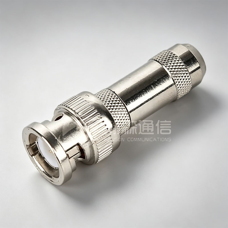
The SMA to BNC adapter is one of the highest-volume adapter configurations in the RF industry. It enables interoperability between the SMA-based RF test equipment world and the BNC-dominated legacy instrumentation infrastructure. Oscilloscopes, signal generators, and spectrum analyzers from the 1980s through the 2000s predominantly used BNC interfaces, while virtually all modern RF modules, filters, and sub-assemblies use SMA.
Critical usage notes for SMA to BNC adapters:
- BNC connectors are rated to 4 GHz maximum — do not use an SMA-to-BNC adapter in signal paths operating above this frequency, even if the SMA side supports 18 GHz.
- Verify impedance: BNC connectors are available in both 50 Ω and 75 Ω versions. Mismatching impedances creates VSWR degradation at all frequencies.
- Torque is critical — hand-tighten BNC bayonet connections fully; apply 5–8 in-lbs torque on the SMA threaded side.
- For outdoor or field use, opt for versions with gold-plated center pins to resist corrosion over time.
When used within its rated frequency range and with proper impedance matching, a quality SMA to BNC adapter introduces less than 0.1 dB insertion loss and achieves VSWR below 1.25:1 — making it effectively transparent to most signal processing systems operating below 3 GHz.
4 Hole Flange Adapter: Panel-Mount Solutions for Permanent Installations
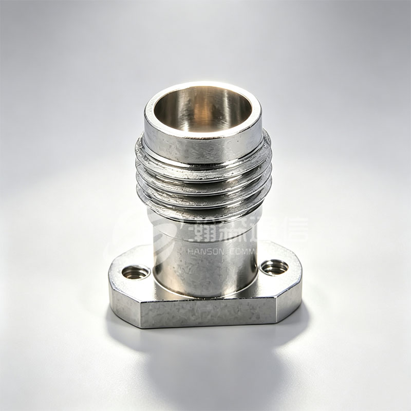
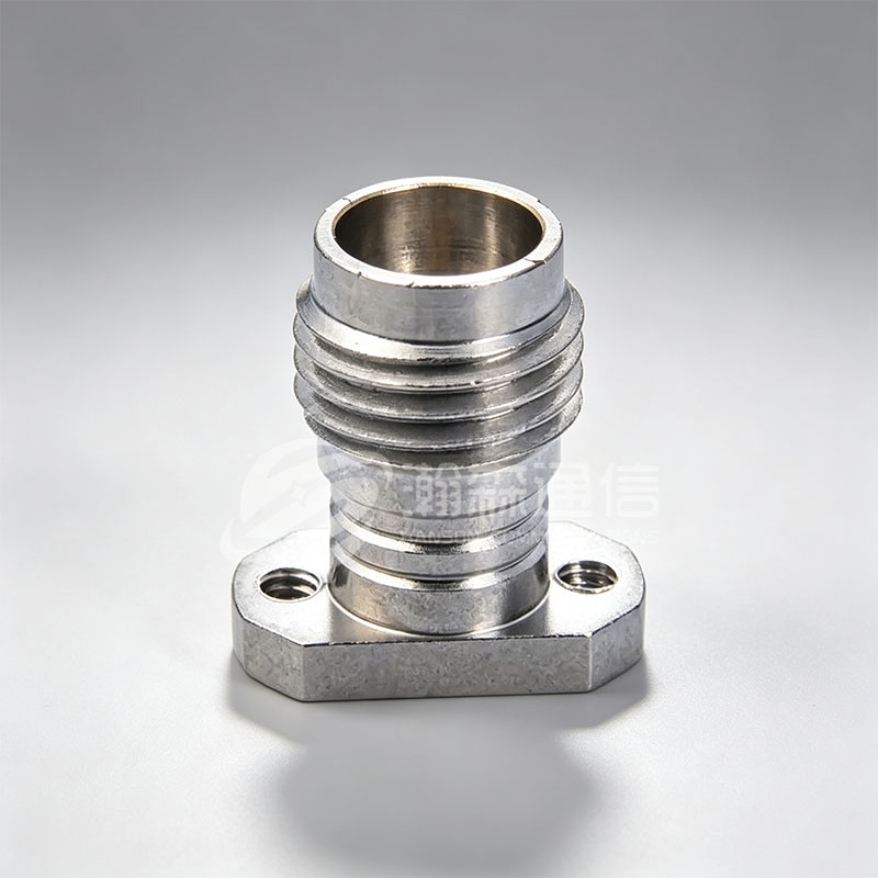
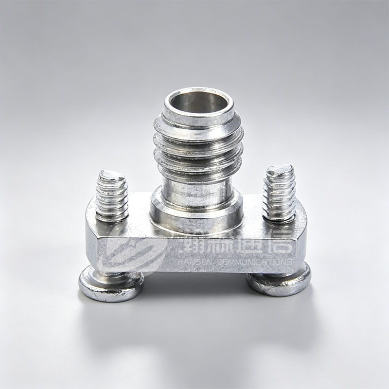
The 4 Hole Flange Adapter is a panel-mount RF interface solution designed for permanent installation through enclosure walls, rack panels, or equipment chassis. Unlike in-line adapters that connect two cable assemblies, flange adapters provide a mechanically rigid, vibration-resistant connection point that maintains consistent impedance and alignment under demanding physical conditions.
The four-bolt pattern (typically on a 25.4mm × 25.4mm or 31.75mm × 31.75mm bolt circle) distributes mechanical load evenly, preventing the torque stress that single-point panel-mount connectors are prone to. This makes 4-hole flange adapters particularly suitable for:
- Aerospace and defense equipment racks where vibration isolation is mandatory
- Communication base station enclosures requiring weatherproof feedthrough connections
- Medical imaging equipment chassis where connector movement would introduce signal artifacts
- Industrial RF systems in high-vibration environments such as motors or CNC machinery
As an ISO9001-certified RF Coaxial Adapter Manufacturer, Ningbo Hanson produces 4-hole flange adapters in N-Type, SMA, TNC, and 7/16 DIN interface configurations, with options for stainless steel, passivated brass, and aluminum alloy body materials depending on corrosion resistance, weight, and conductivity requirements.
Male To Female RF Coaxial Adapter: Gender Configuration and Signal Integrity
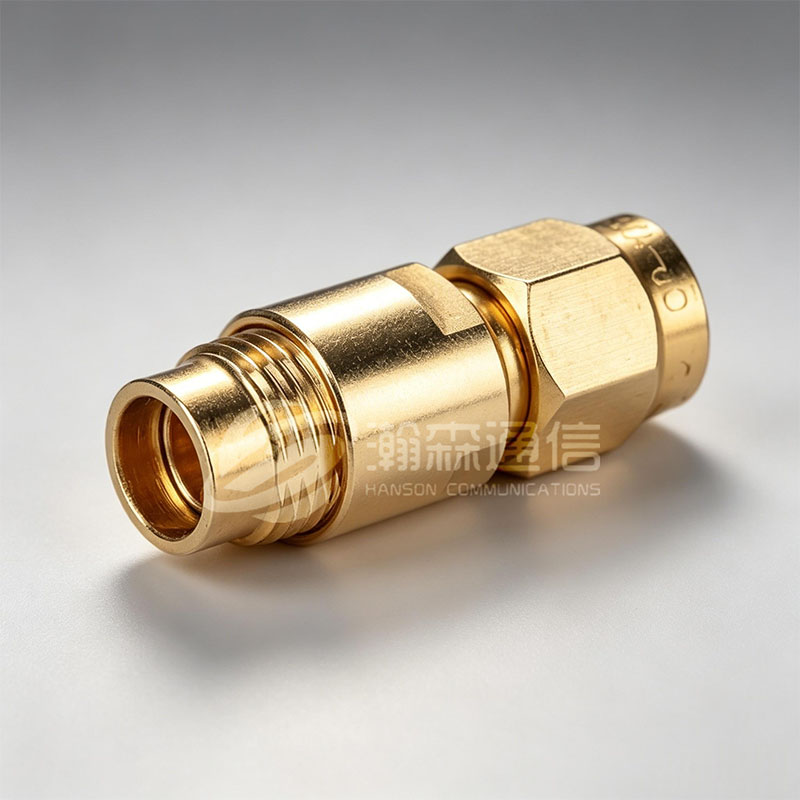
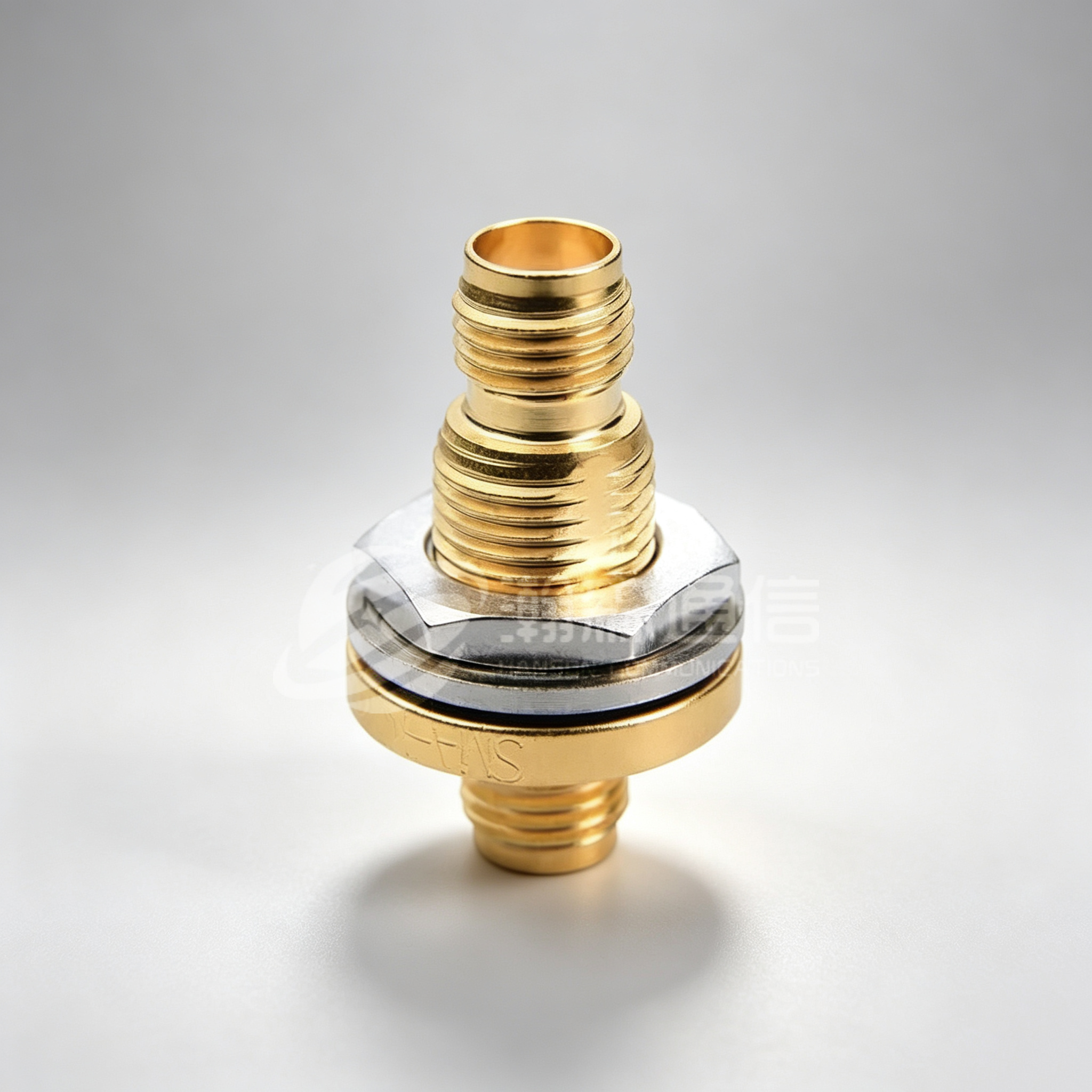
The designation of Male To Female RF Coaxial Adapter — or its reverse, female-to-male — is not just a mechanical distinction. It affects the electrical path length, the type of contact (plug vs. jack), and the mechanical stress distribution during mating. In most RF systems, adapters are used to resolve gender conflicts between cable assemblies and equipment ports, or to extend the reach of a connector without introducing a cable section.
Common gender-conversion scenarios:
- SMA Male to SMA Female: Used to extend or offset a panel-mount connection without replacing the cable assembly
- N-Type Male to N-Type Female: Common in base station installations where feedline polarity needs to be reversed
- TNC Male to SMA Female: Interfaces older TNC-terminated military cables with SMA-equipped modern equipment
One important mechanical note: every mating cycle causes micro-wear on contact surfaces. High-quality adapters use gold-plated (Au) center conductors (typically 0.2–0.5 μm thick) and nickel or passivated brass outer bodies to resist this wear. For test environments where adapters are mated and unmated hundreds of times, specifying a minimum durability rating of 500 mating cycles is prudent.
Performance Radar: SMA vs N-Type vs TNC RF Adapters
Comparative radar chart of SMA, N-Type, and TNC adapter performance across five key dimensions. Scores are normalized for relative comparison.
The radar chart reveals the distinct trade-off profiles of the three most common adapter families. SMA excels in frequency range and low-loss performance, making it the preferred choice for precision and high-frequency signal work. N-Type strikes a strong balance across all five dimensions, particularly in weatherproofing and durability — explaining its dominance in outdoor base station environments. TNC scores highest in vibration resistance, a direct result of its threaded coupling mechanism that locks the mating interface against rotational forces. Understanding these trade-offs allows engineers to make objective, data-supported adapter selections rather than defaulting to the most familiar interface type.
Waterproof RF Connector Selection for Outdoor and Harsh Environments
Any waterproof RF connector or adapter deployed outdoors must meet at minimum IP67 ingress protection (dust-tight and immersion-resistant to 1 meter for 30 minutes) to survive real-world installation conditions. Base station rooftop installations, outdoor distributed antenna systems (DAS), and maritime communication equipment demand connectors that can endure sustained moisture exposure, UV radiation, thermal cycling from -40°C to +85°C, and salt spray corrosion.
Key features to look for in a waterproof RF adapter:
- Captive O-ring or gasket seal integrated into the connector body — not just thread sealant tape
- Passivated stainless steel (grade 304 or 316) or nickel-plated brass body construction
- UV-stabilized dielectric materials (PTFE preferred over standard PE for outdoor dielectrics)
- Salt spray test rating of minimum 500 hours per IEC 60068-2-11
- Third-party IP certification documentation — not just a manufacturer's claim
N-Type connectors are the de facto standard for outdoor RF connections below 11 GHz due to their threaded coupling and large-diameter body, which accommodates robust sealing geometries. For applications above 6 GHz in outdoor settings, 4.3-10 connectors have emerged as a weatherproof alternative combining good high-frequency performance with a compact, self-locking interface.
IP Ratings Required by RF Deployment Environment
Minimum IP protection ratings recommended by deployment environment for RF coaxial adapters and connectors.
The horizontal bar chart illustrates that the required IP rating scales directly with environmental severity. A marine coastal installation demands IP68-rated waterproof RF connectors to withstand continuous salt spray and potential submersion — a standard that many commodity adapters simply cannot meet. In contrast, an indoor rack environment may only require IP44 splash protection. Specifying adapters with marginally adequate IP ratings is a common source of premature field failures, particularly in tropical climates where both humidity and UV exposure are extreme. Always consult your deployment environment data before finalizing the IP specification.
RF Signal Loss Solutions: Minimizing Loss at Every Junction
An effective RF signal loss solution is not just about choosing the right cable — it begins at every adapter, connector, and junction in the signal chain. Signal budget analysis should account for every dB of loss across cables, connectors, adapters, filters, and splitters. For a typical base station receive path with 20 dB of available link budget, losing 2–3 dB to poor adapter choices represents a 10–15% reduction in effective coverage range.
Practical strategies to minimize adapter-induced signal loss:
- Minimize adapter count: Each adapter adds loss and a potential failure point. Design the system to require the fewest possible interface transitions.
- Use precision-grade adapters for critical paths: The receive path and reference oscillator distribution paths are most sensitive to loss and phase noise. Use the best available adapters here, even if it adds cost.
- Verify mating torque: Under-torqued connectors are a leading cause of intermittent loss and high VSWR. Use a torque wrench to apply manufacturer-specified values (typically 7–8 in-lbs for SMA, 12–15 in-lbs for N-type).
- Inspect plating quality: Gold over nickel plating provides the lowest contact resistance. Verify that the center pin plating extends fully into the mating zone, not just the visible surface.
- Request test data sheets: Reputable manufacturers provide actual VSWR and insertion loss data, not just specifications. This measured data reveals real-world performance across frequency.
SMA to TNC Series and N-Type to N-Type Series: Application-Matched Adapter Lines
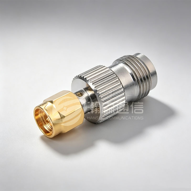
Ningbo Hanson's SMA to TNC Series RF Coaxial Adapter addresses a specific and frequently encountered challenge: connecting modern SMA-terminated equipment to legacy TNC-port military, avionics, and industrial systems. The threaded TNC interface provides a vibration-resistant coupling that the bayonet-free SMA cannot match in high-shock environments, and the SMA-to-TNC adapter family bridges this mechanical disparity without sacrificing electrical performance up to 11 GHz.
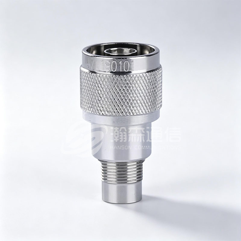
The N-Type to N-Type Series RF Coaxial Adapter serves a different purpose: it provides in-line impedance verification, polarity reversal, or physical offset for N-Type terminated feedlines. These adapters are commonly deployed in cellular tower work to correct cable assembly orientation during installation, and in test labs to create known-good reference standards. With in-line insertion loss under 0.05 dB at 3 GHz and VSWR below 1.15:1, the N-to-N series is suitable for calibration-grade applications.
Typical VSWR at 3 GHz: Adapter Series Comparison
Typical VSWR values at 3 GHz for different RF adapter series. Lower VSWR indicates better impedance matching and less signal reflection.
The column chart highlights that the N-Type to N-Type in-line series achieves the lowest VSWR of the group — 1.12:1 — which is consistent with its use as a reference-grade interface conversion. The SMA to TNC series follows closely at 1.18:1, demonstrating that the transition between these two threaded interfaces can be achieved with minimal impedance discontinuity when manufactured to tight dimensional tolerances. Standard adapters at 1.35:1 VSWR represent the performance floor; while acceptable for low-frequency or non-critical paths, they should not be used in cascaded signal chains where reflections can compound across multiple junctions.
RP SMA Connector: Understanding the Reverse Polarity Interface
The RP SMA connector (Reverse Polarity SMA) looks nearly identical to a standard SMA connector but with the male and female center pin assignments swapped. A standard SMA male has a center pin; an RP-SMA male has a socket. This was originally introduced to prevent non-certified amplifiers from being connected to consumer antennas — but today it simply defines a large installed base of Wi-Fi routers, access points, and consumer RF devices.
Understanding RP-SMA is critical when selecting adapters for RF adapter for antenna configurations in the 2.4 GHz and 5.8 GHz Wi-Fi bands. Connecting a standard SMA cable to an RP-SMA antenna port requires an RP-SMA to SMA adapter — not an SMA extension. The outer threads will appear compatible, but the center conductor will not make contact, resulting in complete signal loss or, worse, a deceptively open-circuit connection that passes DC continuity tests but fails at RF frequencies.
Common RP-SMA adapter configurations include RP-SMA Male to SMA Female, RP-SMA Female to SMA Male, and RP-SMA to N-Type for connecting Wi-Fi and ISM-band equipment to N-Type antenna feedlines. Always mark RP-SMA adapters clearly in your inventory system to prevent accidental mixing with standard SMA stock.
How to Evaluate RF Coaxial Adapter Manufacturers
With hundreds of RF coaxial adapter manufacturers globally, differentiating between commodity suppliers and precision manufacturers requires asking the right questions. The following criteria provide a practical evaluation framework for procurement teams and system engineers.
- Manufacturing integration: Does the supplier own machining, electroplating, and assembly operations in-house? Vertical integration — as practiced by Ningbo Hanson with its own machining workshop, electroplating workshop, and assembly workshop — provides tighter quality control than outsourced production chains.
- Quality certification: ISO9001 certification is a baseline requirement, not a differentiator. Ask for the scope of certification and the most recent audit report date.
- Application depth: Suppliers serving aerospace, medical equipment, and communication base stations operate under more demanding inspection regimes than those serving only commercial electronics.
- Customization capability: Can the manufacturer support non-standard body materials, custom plating, or modified dimensions? This matters for specialized projects where catalog products do not fit.
- Traceability: For critical applications, batch-level material traceability (plating chemistry, raw material certificates) is increasingly required by end customers in defense and medical sectors.
Ningbo Hanson Communication Technology Co., Ltd., with over 30 years of experience in RF coaxial connectors, adapters, and cable assemblies, represents the type of vertically integrated manufacturer that can consistently meet these criteria. The company's product range spans RF coaxial connectors, high-frequency cable assemblies, and low intermodulation cable assemblies — giving customers a single-source partner for complex RF interconnect systems.
Frequently Asked Questions
Q1: What is the difference between SMA and RP-SMA connectors?
SMA and RP-SMA connectors share the same outer thread and body dimensions but have opposite center conductor configurations. Standard SMA male has a pin; RP-SMA male has a socket. They are physically incompatible despite appearing similar, and mixing them results in no RF signal connection. Always verify whether your device uses standard or reverse-polarity SMA before ordering an adapter.
Q2: How many RF adapters can I safely use in series in one signal chain?
There is no fixed maximum, but each adapter adds insertion loss and introduces a small impedance discontinuity. As a practical guideline, avoid more than 3–4 adapters in a single signal path unless each has been verified with insertion loss below 0.1 dB and VSWR below 1.20:1. For precision measurement or calibration chains, the total adapter count should be minimized as aggressively as possible through cable assembly redesign.
Q3: What RF adapter should I use for a 5G outdoor antenna installation?
For 5G sub-6 GHz outdoor antenna installations, N-Type to N-Type in-line adapters or N-Type to SMA adapters are most commonly appropriate, depending on your feedline and radio unit interface types. Ensure the adapter carries an IP67 or IP68 weatherproof rating, uses a captive O-ring seal, and is constructed from nickel-plated brass or stainless steel. For mmWave (24–40 GHz) 5G applications, SMA or 2.92mm (K) interfaces are standard, and adapters must be precision-machined to tighter dimensional tolerances.
Q4: Can I use a 50 Ω SMA adapter with a 75 Ω BNC device?
Physically, a 50 Ω SMA to 75 Ω BNC adapter will mate mechanically, but the impedance mismatch will cause signal reflection and insertion loss that may be unacceptable for sensitive applications. The mismatch loss at the junction is approximately 0.18 dB, and the VSWR at the interface will be around 1.5:1. For video distribution (75 Ω) and RF signal paths (50 Ω), this is a known compromise that many users accept — but for precision measurement or low-noise receive chains, use impedance-matched cables and terminate to a consistent impedance throughout the chain.
Q5: What is a 4-hole flange adapter used for in RF systems?
A 4-hole flange adapter provides a mechanically robust, panel-mountable RF connection point secured by four bolts in a symmetric pattern. Unlike in-line adapters, it is designed for permanent installation through an enclosure panel, distributing mechanical stress evenly to prevent connector damage from cable pull forces or vibration. Common in aerospace equipment racks, communication base station enclosures, and medical device chassis, it combines the electrical performance of the specified connector interface with the mechanical reliability of a flanged chassis mount.
Q6: How do I know if my RF adapter is causing signal loss in my system?
The most direct method is to measure insertion loss and VSWR using a vector network analyzer (VNA) with the adapter connected between the two measurement ports. A rapid increase in insertion loss above the adapter's rated frequency, or VSWR spikes at specific frequencies, indicates a failing contact, damaged dielectric, or dimensional non-conformance. In field environments without a VNA, a signal level meter or power meter comparison across the adapter junction can provide a rough insertion loss estimate. Visually inspect the center pin for bending, the dielectric for contamination, and the plating for corrosion as a first diagnostic step.
Looking For Business Opportunity?
Request for a call today
-

+86-15715730755
-

-

No. 1, Longcao Road, Dongqian Lake Tourism Resort Industrial Zone, Yinzhou District, Ningbo City, Zhejiang, China.
Message
Copyright © Ningbo Hanson Communication Technology Co., Ltd.
