How to determine if an RF coaxial connector needs replacement?
 2025.10.03
 Industry News
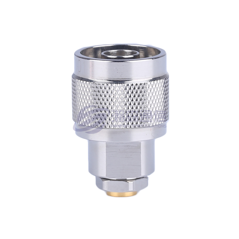
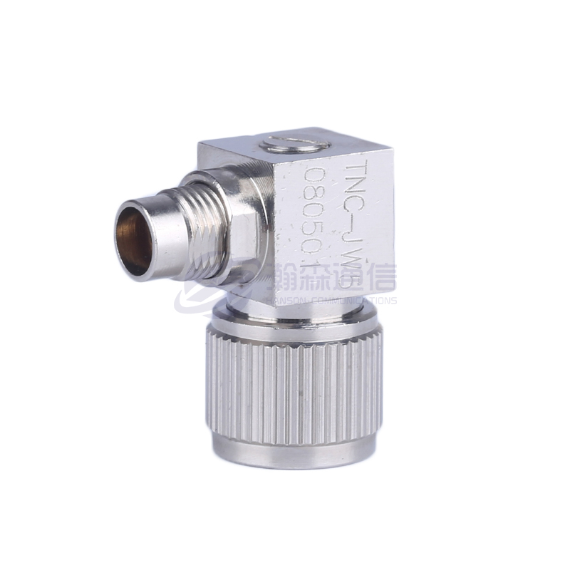
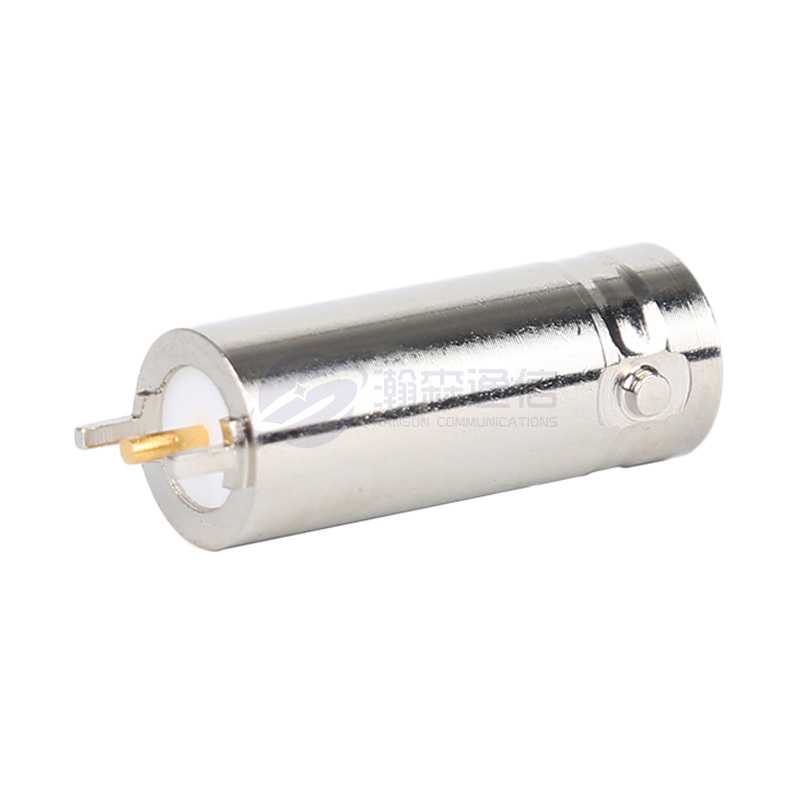
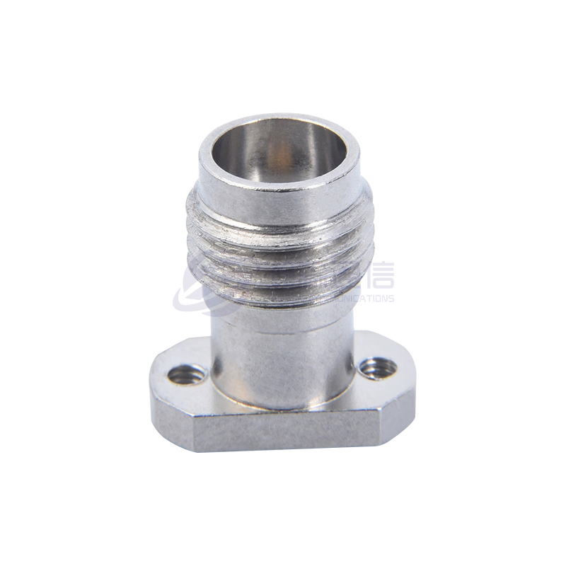
Replacing RF coaxial connectors (such as SMA, N-type, BNC, etc.) requires compliance with strict performance standards, safety regulations, and industry practices to ensure signal integrity, impedance matching, and equipment reliability.
Content
1. Hard standards for replacement
(1). Electrical performance failure
Standing wave ratio (VSWR) exceeds the standard: the test value is >1.5:1 (conventional application) or >1.2:1 (high-frequency precision scenario), indicating impedance mismatch, resulting in signal reflection.
Increased insertion loss: the loss value exceeds the nominal value by more than 0.5dB (for example, the original connector nominal loss is 0.1dB, and the actual measurement is >0.6dB).
Insulation resistance decreases: DC insulation resistance <100MΩ (it may be lower in a humid/polluted environment, but it needs to be combined with industry standards).
(2). Mechanical structure damage
Interface deformation or wear: the center pin is bent, the outer conductor thread is slipped, and the buckle is broken, resulting in a loose connection or inability to lock.
Sealing failure: Waterproof connectors (such as IP67) experience aging of the rubber ring and cracks in the shell, leading to water or dust intrusion.
(3). Decreased environmental adaptability
Corrosion or oxidation: The plating (such as gold plating, silver plating) peels off and the base material (brass, stainless steel) rusts, affecting conductivity and weather resistance.
High-temperature ablation: In high-frequency and high-power scenarios, the contact surface turns black and carbonized due to arc ablation.

2. Preventive standards for recommended replacement
(1). Life cycle
Plug-in and unplug times exceed the limit: The plug-in and unplug life of ordinary connectors is 500~1000 times (such as SMA), and high-end models (such as 7/16 DIN) can reach 5000 times. Even if it is not damaged after exceeding the limit, it is recommended to replace it.
Expired service life: After 3~5 years of continuous use in harsh environments (salt spray, high temperature), industrial-grade connectors should be replaced as a preventive measure even if their performance is normal.
(2). Compatibility issues
Interface standard upgrade: Old models (such as BNC) cannot support the high-frequency requirements of new equipment (such as >4GHz) and need to be replaced with high-performance models (such as N-type or SMA).
Impedance mismatch: Misusing a 50Ω connector to replace a 75Ω system (or vice versa) will result in signal attenuation.
3. Replacement operation specifications
(1). Selection matching
Frequency range: BNC can be used for low frequencies (<1GHz), and SMA or 2.92mm is required for high frequencies (>6GHz).
Power capacity: 7/16 DIN or N-type is used for high-power scenarios (such as radar) to prevent SMA from burning due to power overload.
Environmental protection: For outdoor applications, stainless steel with waterproof rubber rings is selected.
(2). Installation requirements
Torque control: Use a torque wrench to tighten, avoid overtightening (such as 0.5~0.8N·m recommended for SMA) or over-loosening. Soldering/crimping process: Do not use acidic solder paste when soldering the center pin. For crimping connectors, ensure that the cable shield is fully covered.
(3). Post-replacement testing
Required test items: Use a network analyzer to measure VSWR and insertion loss, and a multimeter to check continuity and insulation resistance.
On-site verification: Run the device under actual load and observe the signal noise and connector temperature rise (abnormal heating indicates poor contact).
Request for a call today

 English
 русский
